Below the buttons for the results, there are more buttons that enable showing slabs and plates results along a cut line.
Once the cut lines are drawn (see further), use the two last buttons of the pallet to quickly change the display mode.
 The display mode according to a continuous colours model
 The display mode according to the cut lines
Add a cut line
To add one cut line:
- Click on
 .
. - Draw a line like you would in the geometry. A cut line is always pink.
- End the drawing function with
 or ESC.
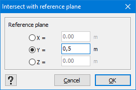
To add multiple cut lines in the same plane (we will be using a cut plane for this):
- Select the elements in which you want a cut line.
- Click on
 .
. - Enter the coordinate for the intersection plane and hit ‘OK’.
Adjusting the length/ slope of a cut line
- Select the cut line and click once on the right mouse button.
- In the floating menu that appears, choose ‘Edit cut line’.

- By default, the begin point A will be fixed (notice the square around point A). Therefore the position of point B will change. If you prefer B fixed and A to be moved, click
 . Here you can also adjust the angle with the X-axis and/ or XZ plan.
Moving a cutline
- Select the cut line and click once on the right mouse button.
- In the floating menu that appears, choose ‘Translate cutline’.

Now you can move the cut line like you would do for a regular line.
With this feature you can move a cut line within the perimeter of the surface.
Divide a cutline
- Select the cut line and click once on the right mouse button.
- In the floating menu that appears, choose ‘Divide cutline’.

Now you can divide the cut line like you would do for a regular line.
Remove a cutline
- Select the relevant cut line(s) and hit
 .
.
