
If the selected element is a surface (slab, plate or wall), you’ll see the dialogue below:

Top part
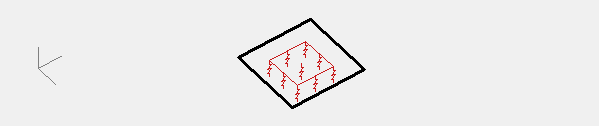
In the top part of this dialogue, you see a graphic representation of the restricted degree(s) of freedom. The orientation of the representation changes with the orientation of the global coordinate system  .
.
Middle part

Here you can restrict the various degrees of freedom directly. For each degree of freedom, using the pull-down menu, you can:
- set the degree of freedom fixed.
This can also be done by checking the check box before the degree of freedom. - enter a spring using a value.
Examples on how to calculate a translational spring, can be found here. - enter a function (see below).
- enter the soil layers to be used.
This article explains how to add soil layers to your model.
This article explains how Diamonds handles soil layers in the elastic analysis.
You can define non-linear supports (compression or tension only). For example, in the global Y-direction, this means that an upwards or downwards displacement of the structure is not hindered.
Custom function
A rigidity diagram presents the displacement (or angular displacement) in relation to the applied force (reaction force, moment, normal force or shear force). The definition of a rigidity diagram is at the end of a bar is similar to the definition for a support.
- Select the option “Function” from the drop down menu.
- Either choose one of the existing functions or define a new one by clicking on
 .
.
A new dialogue appears. - Click
 .
.
- Name the function.
- For each sign of the reaction, choose if:
- the reaction cannot be transferred = free
- the reaction can be transferred = fixed
- the reaction can be transferred linear = value
- the reaction can be transferred variable = user defined
When you choose this option, keep the following remarks in mind:- The function must always go through the origin.
- Avoid (almost) perfect horizontal or vertical branches in the graph.
They describe a relation, not a function y= f(x). One x-value can lead to multiple solutions y or multiple x-values lead to the same solution. This causes arithmetic problems.
Use gently sloping branches instead.
- You can save a defined function in a TXT-file using the button
 .
.
An existing function (TXT format) can be loaded via .
.
| Example of a custom function on a bar end | Example of a custom function on a support |
|---|---|
 | 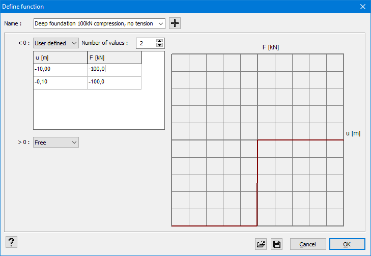 |
| The diagram shows that the rotation rigidity M/φ is constant as long as the applied moment is less than 45,4kNm. Once the moment is exceeded, the rigidity varies according to M. If the moment exceeds 68,2kNm, a plastic hinge is formed because an additional moment produces an angular deformation infinitely large. | The foundation can’t bear tension and only 100kN compression. The rigidity diagram should lay in the 1st and 3rd quadrant because in the formula F=k∙x the spring constant k cannot take on a negative value. If the function does not have a valid range, a red message will appear below this window. |
Soil layers
Bottom part
Finally you can define the supports relative to the orientation of the plate.