You can open the dialogue for the surface properties two ways:
- either double-click one surface in the ‘Geometry’ configuration,
- either select one (or more) surface(s) and click on
 .
.
In both cases, the following dialogue appears:

With the buttons ![]() and
and ![]() you can export and import the properties respectively. This way you can easily reuse self-defined plate types. Keep in mind that the material and concrete cover are not imported / exported.
you can export and import the properties respectively. This way you can easily reuse self-defined plate types. Keep in mind that the material and concrete cover are not imported / exported.
General
In the upper part of this dialogue box you define/change:
- The name of the surface.
- Shape
Every surface defined in Diamonds, is isotropic by default. The properties are identical in all directions. But you can change that behaviour by chosing a different plate type .
.
A list of the different plate types and their properties is given in the table below.
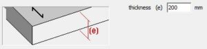
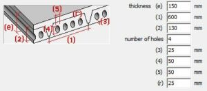
Depending on the chosen shape, you’ll have to enter various dimensions. A drawing illustrates the required dimensions.
| Icon | Name & description | Which thickness bears in one or two direction(s)? | Examples |
|---|---|---|---|
| Isotropic slabs – slabs which have the same properties in all the directions. | 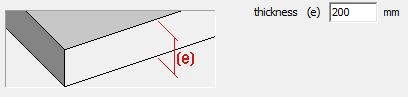 (e) in two directions (e) in two directions | 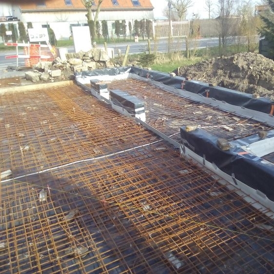 | |
| Pre-slab floors – floors composed of pre-slabs (which bear in one direction) on which an isotropic concrete layer is cast. | 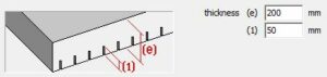
(1) in one direction | 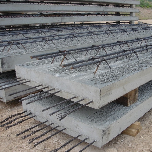 | |
| Slabs positioned in a single direction – slabs without any rigidity in the direction perpendicular to the main direction. |
 (e) in one direction | 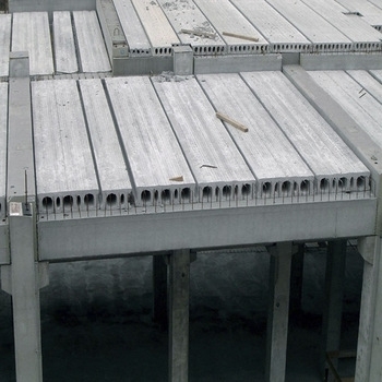 | |
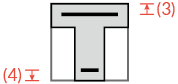
| Ribbed floors with ribs in one direction – floor elements with ribs in the longitudinal direction | 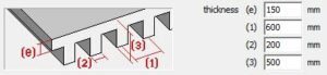 (e) in two directions (e) in two directionsthe ribs in one direction | 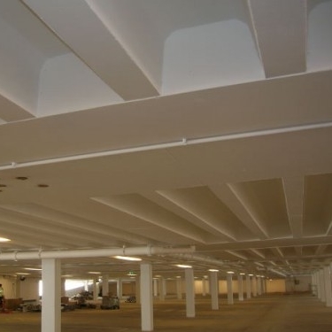 | |
| Ribbed floors with ribs in two directions – floor elements with ribs in two directions | 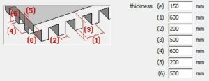 (e) in two directions (e) in two directionsthe ribs in two directions | 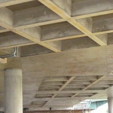 | |
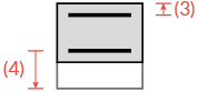
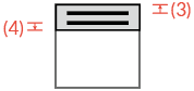
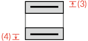
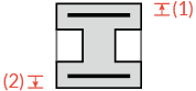
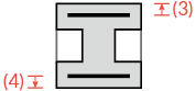
| Unfilled multicellular slabs – unfilled floors/ slabs whose slots go in one main direction. | 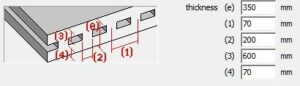 (3) and (4) in two directions (3) and (4) in two directionsthe ribs in one direction | – | |
| Unfilled floors/ slabs– floors whose slots are placed according to a rectangular grid | 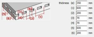 (3) and (4) in two directions (3) and (4) in two directionsthe ribs in two directions |  | |
Hollow core slab – floor build up from hollow core slabs (which bear in one direction) on which an isotropic concrete layer is cast
|  (e) in one direction (e) in one direction | | |
| Diaphragm – plate without any bending stiffness | this plate type (a membrane) has no bending stiffness, only axial stiffness | – | |
| Arbitrary plate defined based on the stiffness matrix | bearing direction is imposed by the user-defined stiffness matrix | 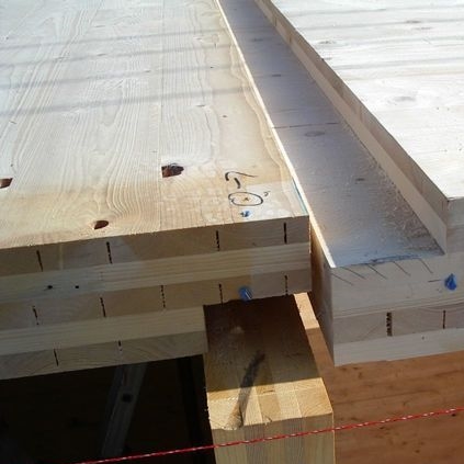 | |
| Opening or delete plate | – | – |
Stiffness matrix
Diamonds is a Finite Element Method (FEM) based software program. The FEM chops the structure in a finite number of elements, which will then be logically linked to each other. There are a number of requirements to these links, depending on the type of element (beam, column, plate, wall, … ). In any case, it is required that the nodes of the elements displace together.
This method allows to approximate the behavior of a complex structure by solving a matrix equation. The matrix equation expresses the relation between the elements in the structure. In case of a linear static analysis, the matrix equation writes as follows:
![\[\underbrace{\left[ Q \right]}_\text{load in mesh nodes} =\overbrace{\left[ K \right]}^{\text{stiffness matrix}} \cdot \underbrace{\left[ U \right]}_\text{displacement in mesh nodes}\]](https://support.buildsoft.eu/wp-content/ql-cache/quicklatex.com-9af8b38243e84af67975a6a0248e251d_l3.png "Rendered by QuickLaTeX.com")
The matrix equation contains a stiffness matrix [K], a matrix with node displacements [U] and a matrix with node loads [Q].
The stiffness matrix [K] will condition the behavior of the elements (beam, column, plate, wall, … ). Without going further into detail on the derivation, we assume that the stiffness matrix [K] for a slab or plate looks as follows:
![\[\left[K \right]=\begin{bmatrix}d_{xx} & d_\upsilon & 0 & 0 & 0 & 0\\d_\upsilon & d_{zz} & 0 & 0 & 0 & 0\\0 & 0 & d_{xz} & 0 & 0 & 0 \\0 & 0 & 0 & D_{xx} & D_\upsilon & 0\\0 & 0 & 0 & D_\upsilon & D_{zz} & 0\\0 & 0 & 0 & 0 & 0 & D_{xz} \\\end{bmatrix}\]](https://support.buildsoft.eu/wp-content/ql-cache/quicklatex.com-190a175fca1fe0d948d60b24d392492d_l3.png "Rendered by QuickLaTeX.com")
The factors with ‘d’ describe the behavior for membrane action (= normal forces, the factor with ‘D’ describe the behavior for bending. The factors for shear are not mentioned here. The table below gives an overview of these factors for a number of plate types:
| Two way slab | One-way slab | Diaphragm | |
|---|---|---|---|
 |  | | |
 | | 0 | |
 |  | 0 | |
 |  | 0 | |
 |  | | 0 |
 | | 0 | 0 |
 |  | 0 | 0 |
 |  |  | 0 |
For plates bearing in one direction the torsional rigidity is a function of the width-thickness ratio (= b/e) of the strips from which the plate is constructed. Therefore, the torsional rigidity of plate bearing in one direction is expressed as a percentage t of the torsional stiffness of an isotropic plate.
The table below calculates the torsional rigidity of a plate bearing in one direction and the torsional factor for different ratio’s of b/e.
![\frac{b}{e} \text{[-]}](https://support.buildsoft.eu/wp-content/ql-cache/quicklatex.com-55845b157c8a9a4d3a423ddc15f185bb_l3.png "Rendered by QuickLaTeX.com") | ![D_{xz1}\text{[kNm]}](https://support.buildsoft.eu/wp-content/ql-cache/quicklatex.com-4c45b5d3ddf621d59302aafc78c1cc5a_l3.png "Rendered by QuickLaTeX.com") |  |
|---|---|---|
| 1 | 3694 | 42% |
| 2 | 6004 | 69% |
| 3 | 6909 | 79% |
| 4 | 7367 | 84% |
| 6 | 7825 | 90% |
| 10 | 8193 | 94% |
From the table above we can conclude that for a plate bearing in one direction with strips of thickness 20cm and width 60 cm b/t=60/20=3, about ≈80% of the torsional stiffness of an isotropic plate is reached. In this case, you should fill in 80% in the window with the plate properties.

Material and concrete cover
- Select a material for the plate using the drop-down list. It contains all the materials present the Material Library.
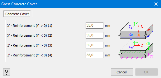
- For a concrete surface, you also need to indicate the gross cover.
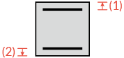
The gross cover is understood as the distance between the reinforcements centre of gravity and the upper or lower edge of the cross-section.
Click to open the following dialogue.
The table below gives an overview of where Diamonds assumes the reinforcement is in a certain plate type. It also shows for which plates Diamonds can calculate the stresses and for which ones it can’t.
| Icon | Display of stresses | Reinforcement zones | |
|---|---|---|---|
| principle x’-direction | secundairy z’-direction | ||
| ✓ |  |  | |
| ✓ |  |  | |
| ✓ | | – | |
| ✗ |  |  | |
| ✗ |  |  | |
| ✗ |  |  | |
| ✗ |  |  | |
| ✗ | reinforcement calculation not possible | ||
| ✓ | reinforcement calculation not possible | ||
| ✗ | reinforcement calculation not possible | ||
Notes:
- For some plate types (like ribbed slabs), the cross-section (= the stiffness) is not constant over the width (or length) of the plate. The increased stiffness is smeared open over the surface of the plate.
This smeared out stiffness makes it impossible to calculate stresses. - For a préslab
 the option “Crack calculation with reduced height” will be visible. More info in this article.
 - It is not possible to model pre- or post-tensioning in our software.
Local axes
This local coordinate system of a surface is important because the representation of the results (in particular upper and lower reinforcement) depends on the chosen oriëntation.
To show the local coordinate system of a surface:
- Close all dialogues and go to the Geometry configuration
 .
. - Click on the Configuration settings
 .
.
In the column “Surfaces” check the option “Local coordinate system“.

- The x’-axis will always run parallel to the main bearing direction of the slab. If a slab has a preferred bearing direction (like a one-way slab), the x’-axis will always be parallel to the arrow drawn in the plate.
The z’-axis will always run parallel to the secundary bearing direction of the slab.
The y’-axis determines the upper and lower side the slab. The direction in which the y’-axis is pointing, it the upper side. You’ll need this when evaluating the reinforcement in walls.

When you create a plate, the x’-axis of a plate will always be parallel to the global X-axis by default. However, this is not always desired. The options at the bottom of this dialogue ![]() , allows you to change that.
, allows you to change that.
- Local xz axes orientation
This option will rotate the local coordinate system of the slab in a horizontal XZ plane. - Local y-axis orientatie
This option will flip the direction of the y’-axis. It comes in handy when defining horizontal ground- or waterpressures.
