Steel and timber parameters
Strength verification
The resistance check verifies that the calculated internal forces do not exceed the limits imposed by the standard. Different checks are performed according to Eurocode (EN1993-1-1), namely those listed below. 1•2•Build performs these verifications for all combinations in ultimate limit state.
Steel (EN 1993-1-1)
- Axial tension (§6.2.3)
- Axial compression (§6.2.4)
- Bending My’ (§6.2.5)
- Bending Mz’ (§6.2.5)
- Shear force Vz’ (§6.2.6)
- Shear force Vy’ (§6.2.6)
- Torsion Mx’ (§6.2.7)
- Bending My’ and shear force Vz’ (§6.2.8)
- Bending Mz’ and shear force Vy’ (§6.2.8)
- Double bending and axial force (§6.2.9)
- Double bending with axial force and shear force (§6.2.10)
Timber (EN 1995-1-1)
- Axial tension (§6.1.2)
- Axial compression (§6.1.3)
- Bending My’ (§6.1.6)
- Shear force Vz’ (§6.1.7)
- Bending My’ + axial tension (§6.2.3)
- Bending My’ + axial compression (§6.2.4)
To view the result of the strength verification, you click on the button![]() in the icon pallet. The result is always expressed as a percentage of the total capacity of the bar against the considered loads. For more details, double click a bar:
in the icon pallet. The result is always expressed as a percentage of the total capacity of the bar against the considered loads. For more details, double click a bar:
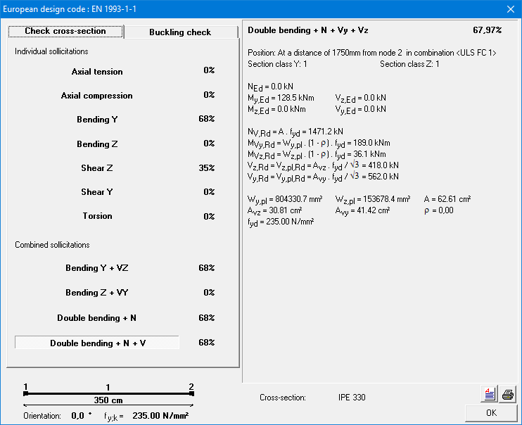
This dialog summarizes all the performed checks. The check that resulted in the highest percentage is shown in bold. For this check, the intermediate results are shown on the right.
To view the details of the other checks, click on the line containing the check with its percentage.
Stability verification
The stability check verifies that the calculated internal forces do not cause buckling or lateral torsional buckling. Different checks are performed according to Eurocode, namely those in the table below. 1•2•Build performs these verifications for all combinations in ultimate limit state.
Steel (EN 1993-1-1)
- Buckling around the strong axis (§6.3.1)
- Buckling around the weak axis (§6.3.1)
- Torsional buckling (§6.3.1)
- Lateral torsional buckling (§6.3.2)
- Buckling around the strong axis due to My’, Mz’ and N (§6.3.3)
- Buckling around the weak axis due to My’, Mz’ and N (§6.3.3)
Timber (EN 1995-1-1)
- Buckling in and out of the plane (§6.3.2)
- Lateral torsional buckling (§6.3.3)
To view the result of the stability verification, you click on the button ![]() in the icon pallet. The result is always expressed as a percentage of the total capacity of the bar against the considered loads. For more details, double click a bar:
in the icon pallet. The result is always expressed as a percentage of the total capacity of the bar against the considered loads. For more details, double click a bar:
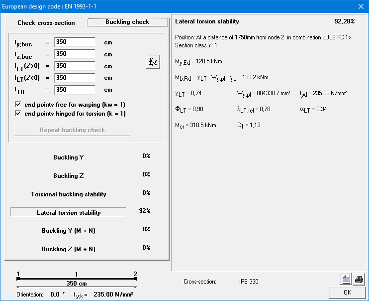
This dialog summarizes all the performed checks. The check that resulted in the highest percentage is shown in bold. For this check, the intermediate results are shown on the right.
To view the details of the other checks, click on the line containing the check with its percentage.
At the top left of this window, there are some other important parameters for the stability control:
- ly,buc and lz,buc are the buckling lengths about the strong and weak axis, respectively. They are automatically calculated by 1•2•Build, but you can always change the value by clicking in the appropriate field or by clicking the button
 .
. - lLT (z’ > 0) and lLT (z’ < 0) are the lateral torsional buckling lengths at the top flange and at the bottom flange respectively. Depending on the sign of the bending moment My’ either the bottom or the top of the bar can be under compression. That is why 1•2•Build allows to assume a different lateral torsional buckling lengths for the top and bottom.
- k and kw are factors that take the effect of the different types of boundary conditions on the elastic cricital moment Mcr into account. 1•2•Build assumes a safe value, but you can always change it.
- k is equal to 1 if the lateral deflection is not prevented at either support point. Otherwise, it is assumed that both end points allow rotation around the weak axis of the profile (k = 0,5).
- kw takes into account whether the cross-sections at the ends are prevented from warping. kw=1 is recommended unless special provisions are made.
From the moment you change one of the parameters above, you need to redo the stability verification by clicking on the button ‘Recalculate buckling risk’.
Optimisation
In order to always suggest the most optimal steel profile or the most effective timber cross-section, 1•2•Build repeats the previous steps (elastic calculation, followed by resistance and buckling checks) several times in an iterative process. A particular profile choice will be considered optimal when the percentages for resistance and buckling are as close to 100% as possible, without exceeding it.
1•2•Build therefore includes an optimisation procedure that searches for the most optimal section based on the forces obtained. The search for the most optimal section is done in two ways:
- for steel or timber sections selected from the library, 1•2•Build searches within the selected group (HEA, IPE, etc.) for the profile that most closely approximates the target value of 100% with the calculated section forces – naturally taking into account the dead weight of the selected sections;
- or timber sections defined on the basis of a fixed width or height, 1•2•Build determines the optimal dimensions by adjusting the height or width (depending on the option selected) so that the target value of 100% is approximated as closely as possible with the calculated shear forces – naturally taking into account the dead weight of the sections selected.
This optimisation procedure runs automatically once you have started the dimensioning process, unless you have selected a specific section. In that case, 1•2•Build will limit itself to an elastic calculation followed by a resistance and buckling check. You must then remember to verify the results of this check.
