We select the command “Cross sections…” in the menu “Lay-out” under the submenu “Comments” if we wish to modify the information of the bars and the stirrups in the cross sections. The following dialog is now visualised on the screen:
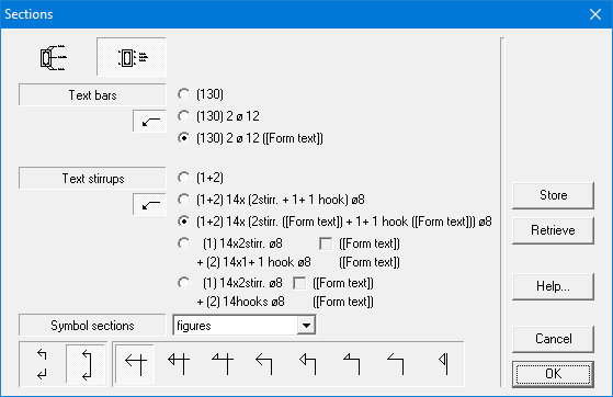
Indicate which information should be placed on the plan.
- The buttons under “Text bars” and “Text stirrups” serve for whether or not using indication lines to the bar or to the stirrup. The choice possibilities for the information are analogous to those for the longitudinal view.
- By clicking on one of the cross section representations at the top of the dialog box, we can change the representation of the cross section. We can choose between
- an indication of the reinforcement according to the position in the cross section (whether or not with indication lines)
- or an indication of the reinforcement by placing the number of the list immediately with the cross section drawing and a list next to it with in order the numbers of the list and their belonging information.
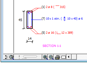
The section drawing looks as visualised below if we choose the first possibility:
A pull-down menu offers the possibility to indicate the section with figures, capital letters or small letters. We can also choose whether the section indication should be drawn of the whole height of the beam or just in the region of the upper and lower fibres. There are also a lot of possibilities to represent the observation direction of the cross section. For the explanation of “[Form text]” see this article.
With the button “Store” you can save the current input as default. With the button “Retrieve” you can replace the current content of the dialog with the default values.
Selecteer in het menu “Layout” onder het submenu “Tekst & uitleg” het derde commando “Doorsnedes…” om de informatie bij de staven en de beugels in de doorsnedes te veranderen. Op het scherm verschijnt nu het volgend dialoogvenster:
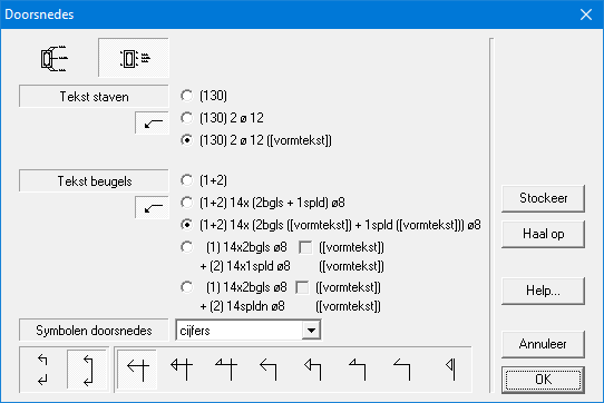
Kies welke informatie op het plan geplaatst wordt.
- De knoppen onder “Tekst staven” en “Tekst beugels” dienen voor het al dan niet gebruiken van verwijzingslijnen naar de staaf of de beugel. De keuzemogelijkheden voor de informatie zijn analoog aan deze voor het
- Door één van de twee knoppen linksboven aan te klikken, wordt de voorstelling van de doorsnede gewijzigd. Hierbij is er de keuze in
- ofwel een aanduiding van de wapening volgens de positie in de doorsnede (al dan niet met verwijzingslijnen);
- ofwel een aanduiding van de wapening door het plaatsen van het borderelnummer onmiddellijk bij de doorsnede-tekening en een lijst ernaast met in volgorde de borderelnummers en de bijhorende informatie.
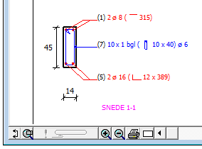
De eerste keuze selecteren zou als gevolg hebben dat de doorsnede-tekening er nu als volgt zou uitzien:
Via een keuzemenu is het mogelijk aan te duiden of de doorsnedes benoemd worden met cijfers, hoofdletters of kleine letters. Kies ook of de snedeaanduiding moet doorlopen over de gehele balkhoogte of enkel maar ter plaatse van boven- en ondervezel. Het programma voorziet eveneens diverse mogelijkheden voor de voorstelling van de kijkrichting van de doorsnede. De verklaring van “[vormtekst]” kan je hier vinden.
Met de knop “Stockeer” bewaar je de huidige inhoud als default inhoud. Met de knop “Haal op” vervang je de huidige inhoud van het dialoogvenster door de default inhoud.
Si vous souhaitez modifier les informations des barres et des étriers dans les coupes, sélectionnez la commande “Coupes…” dans le sous- menu “Annotations” du menu “Format“. La fenêtre de dialogue illustrée est alors affichée à l’écran :

Vous pouvez choisir les informations que vous souhaitez voir figurer sur le plan.
- Les boutons à cocher se trouvant derrière “Texte barres” et “Texte étriers” permettent d’utiliser les lignes de message des barres ou des étriers. Les possibilités d’option sont similaires à celles décrites pour la vue longitudinale.
- En cliquant sur une des deux cases se trouvant au coin supérieur gauche, vous pouvez modifier la représentation de la coupe. Vous pouvez indiquer les armatures
- soit en plaçant les informations suivant leur position dans la coupe (avec ou sans lignes de message) ;
- soit en plaçant le numéro du bordereau de l’armature tout près de cette armature et en ajoutant, juste à côté du dessin de la coupe, une liste, avec les informations des armatures, classée selon l’ordre des numéros de bordereau.
Si vous sélectionnez la première option, le dessin de la coupe ressemblera à celui représenté à la prochaine figure :

A l’aide d’un menu d’options, vous pouvez indiquer si le nom des coupes doit être composé de chiffres, de majuscules ou de minuscules. Vous pouvez également choisir si les lignes doivent se poursuivre sur toute la hauteur de la poutre ou uniquement sur les faces supérieures et inférieures de la poutre. Vous avez différents choix pour le symbole de coupe. Pour la définition de “[texte de forme]”, veuillez voir ici.
Avec le bouton “Sauver“, vous enregistrez le contenu actuel comme contenu par défaut. Avec le bouton “Appeler” vous remplacez le contenu actuel de la boîte de dialogue par le contenu par défaut.
