ENNLFR
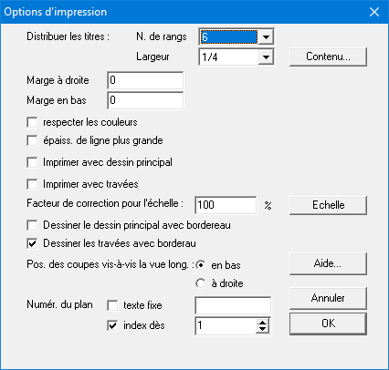
Select the command “Print options…” in the “File” menu. On the screen appears the following dialog box :

- As already mentioned before, the reinforcement plan is automatically framed.
In addition, it’s also possible to add a title frame at the bottom of the plan (left or right, see 5.6). This title frame can contain at the maximum 6 data frames: the address data of the project, the owner, the architect, the contractor, the engineer and the general data (the used materials, date, scale(s) and plan numbers). Also referred to as “Project data” (which you can edit through the option “Modify…” in the menu “File”).
Specify the number of horizontal rows over which this data should be spread (1,2,3 or 6) and also what fraction of the page width will be taken by the title frame. Than you can indicate which information should be shown in which frame by clicking on the button “Content…”. Select the desired information in each frame by means of a pull-down menu:
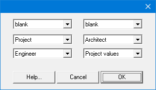 The lay-out of the dialog box adapts to the number of horizontal rows. Frames which content was set to “blank” are not drawn (neither is their frame). In this way you can define the number of frames, their size and their position.
 - Right margin and bottom margin can be set to reduce the rest space in the frame. The drawings of the cross sections can be set at the right side of the longitudinal view or beneath it. Reinforcement that do not fit on one page will automatically be split over a number of pages, with a small overlap and with an indication of this overlap by small horizontal and/or vertical lines.
- If the option “respect colours” is unchecked, all elements will be sent to the printer in black.
- If the scale on the printout does not fully correspond with the defined scale, a correction factor can be set.
- Plans can be numbered with a fixed text and an index number which is automatically increased during printing. In this way the printed plans are numbered in a continuous way.
Ga naar het menu “Archief” – “Printopties…” om de printopties in te stellen. Op het scherm verschijnt volgend dialoogvenster:

- Bij het rechtstreeks printen wordt het wapeningsplan van de balk automatisch omkaderd. Bovendien kunnen alle administratieve dossiergegevens in een hoofdingkader rechtsonder voorgesteld worden. Dat hoofdingkader kan maximaal uit zes gegevenskaders bestaan: de adresgegevens van het project, de bouwheer, de architect, de aannemer, de ingenieur of de algemene gegevens over staal- en betonkwaliteit, datum, schalen en plannummers. Ook wel “Dossiergegevens” genoemd (te wijzigen via de optie “Wijzig …” het menu “Archief”).
Geef op over hoeveel horizontale rijen deze kaders gespreid dienen te worden (1,2,3 of 6) en het hoeveelste deel ze van de breedte van een bladzijde mogen beslaan. Geef vervolgens op welke informatie in welke kader komt te staan door op de knop “Inhoud…” te klikken. Duid met behulp van een keuzemenu voor elke kader haar inhoud aan:
 De lay-out van dit dialoogvenster past zich aan naar gelang het aantal horizontale rijen. Kaders wiens inhoud als blanco worden opgegeven, worden niet getekend (dus die kader zelf ook niet!). Op die manier is er de vrijheid om het aantal kaders, hun grootte en positie vrij te bepalen.
 - Rechter– en ondermarge zijn instelbaar, zodat de “restruimte” binnen de kader van het wapeningsplan kan gereduceerd worden. Het uitprinten van de hoofdtekening is facultatief. De dwarsdoorsnedes kunnen rechts of onder het langsaanzicht geplaatst worden. Wapeningsplannen die niet op één enkele bladzijde passen, worden automatisch over verschillende bladzijden verdeeld, met kleine overlapping en aanduiding hiervan met behulp van horizontale en verticale knipaanzetten.
- Indien de optie “Kleuren respecteren” uitgevinkt staat, worden in het zwart doorgestuurd naar de printer.
- Als de schaal op de afdruk niet overeenstemt met de ingestelde schaal, kan hiervoor een correctiefactor ingevoerd worden.
- Plannen kunnen genummerd worden met een vaste tekst en index die automatisch verhoogd wordt bij het uitprinten. Zo krijgen na mekaar uitgeprinte plannen een opeenvolgende nummering.
Pour choisir les options d’impression, allez vers le menu “Fichier” – “Options d’impression…” . La fenêtre ci-dessous apparaît à l’écran :
- Les plans de ferraillage directement imprimés ou tracés à partir de ConCrete Plus sont automatiquement encadré.
En plus, on peut représenter toutes les données administratives du dossier dans un cadre au coin inférieur droit du plan. Ce cadre peut être divisé en six cadres de données au maximum : les coordonnées (nom, adresse, etc…) du projet, du maître de l’ouvrage, de l’architecte, de l’entrepreneur, de l’ingénieur et les données générales concernant la qualité de l’acier, du béton, la date, les échelles et le numéro du plan (indiqué comme “Valeurs du dossier“).
Nous indiquons le nombre de rangs horizontaux pour la répartition de ces cadres (1,2,3 ou 6) et la partie de la largeur de la page qu’ils peuvent occuper. Pour indiquer quelle information doit être mise dans quel cadre, nous cliquons avec la souris sur le bouton “Contenu…”. Dans la fenêtre de dialogue qui s’affiche à l’écran (Figure 76) nous sélectionnons par chaque cadre le continu à l’aide du menu déroulant.
La fenêtre de dialogue est adaptée au nombre de rangs horizontaux. Des cadres qui ont comme contenu l’indication “Rien”, ne sont pas dessinés (le cadre non plus!); ainsi, nous avons une plus grande liberté pour déterminer le nombre des cadres, leur grandeur et leur position. - La marge à droite et en bas sont modifiables de sorte que nous puissions réduire “l’espace vide” à l’intérieur du cadre du plan. Vous n’êtes pas obligés d’imprimer le dessin principal. En plus, vous pouvez choisir la position des coupes par rapport à la vue longitudinale. Des plans d’armatures qui ne peuvent figurer sur une page, sont automatiquement répartie sur différentes pages, avec un petit recouvrement et une indication de ceci à l’aide de petits traits horizontaux et verticaux.
- Si l’option “respecter les couleurs” n’est pas cochée, tous les éléments seront envoyés à l’imprimante en noir.
- Si l’échelle sur papier ne correspond pas à l’échelle souhaitée, vous pouvez le corriger par un facteur de correction.
- La numérotation des plans peut être composée d’un texte fixe et d’un indice qui est automatiquement incrémenté pendant que les différents plans sont imprimés. Ainsi, nous obtenons de plans qui sont numérotés l’un après l’autre.
