In this window you can check the diagrams that should appear in the window ‘Diagrams’. The height scale of the graphs is always determined such that all desired graphs nicely distributed evenly across the window.
The diagrams of the rotation angles and of the deflections are calculated according to the linear-elastic method. If we select the option “with cracked sections“, the program does not only calculate the elastic deflection, but also a more sophisticated deflection which takes the cracked state into account. This last one is represented in red in the Diagrams window.
The deflection in the serviceability limit state under the quasi-permanent combinations should be limited to 1/250 of the span length, where the deflection can cause damage to other elements even 1/500. Is the option “after creep ” designated, then the creep will be charges in the elastic analysis and in the calculation of the cracked state.
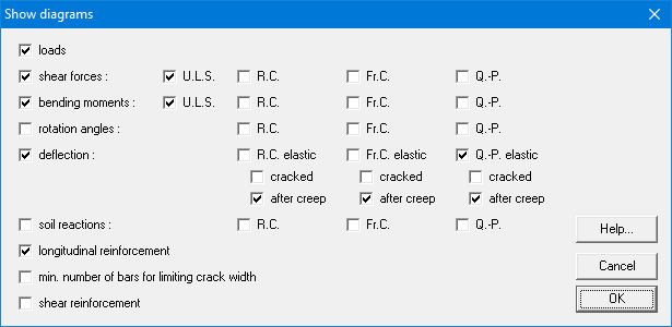
Since there are no rod diameters chosen yet, the calculation of crack width is only based on the theoretically required reinforcement sections. The crack width depends on the diameter and number of the rods, such that a calculation of crack width cannot be approached from theoretical reinforcement sections. The limitation of crack width in Concrete leads to a somewhat reverse calculation: ConCrete calculates how many bars at least should be placed so that the maximum allowable crack width is not exceeded, assuming all the very minimum reinforcement section is placed and that all bars will have the same diameter.
In dit venster kan aangekruist worden welke grafieken in het “Grafieken“- venster getoond moeten worden. De schaal van de grafieken wordt steeds zodanig bepaald dat alle gewenste grafieken mooi evenredig over het venster verdeeld worden.
De hoekverdraaiings- en doorbuigingslijn worden berekend volgens de lineair-elastische methode. Is de optie “gescheurd” aangeduid, dan berekent het programma ook de doorbuiging in gescheurde toestand, rekening houdend met de theoretisch vereiste wapeningssecties. Deze laatste doorbuiging wordt in het “Grafieken“-venster in het rood voorgesteld. De doorbuiging in de gebruiksgrenstoestand onder de quasi-permanente combinaties dient beperkt te worden tot 1/250 van de overspanningslengte; in geval de doorbuiging schade kan veroorzaken aan andere elementen zelfs tot 1/500. Is de optie “na kruip” aangeduid, dan wordt de kruip zowel bij de berekening in gescheurde toestand als bij de elastische berekening in rekening gebracht.
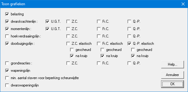
Vermits in ConCrete nog geen staafdiameters gekozen worden, kan de berekening van de scheurwijdte zich enkel baseren op de theoretisch vereiste wapeningssecties. De scheurwijdte is echter in die mate afhankelijk van de gekozen diameters en hun aantal, dat een berekening van de scheurwijdte op zich niet kan benaderd worden vanuit theoretische wapeningssecties. De beperking van de scheurwijdte in ConCrete leidt dan ook tot een enigszins omgekeerde berekening: ConCrete berekent namelijk hoeveel staven er minstens geplaatst dienen te worden om de maximum toegelaten scheurwijdte niet te overschrijden, ervan uitgaand dat overal juist de minimaal vereiste wapeningssectie geplaatst wordt en dat alle staven dezelfde diameter zullen hebben.
Dans cette fenêtre, vous pouvez sélectionner les graphiques à afficher dans la fenêtre “Graphiques”. L’échelle des diagrammes est toujours déterminée de façon que les diagrammes sélectionnés soient correctement affichés.
Les diagrammes de la déformée et des angles de rotation sont calculés selon la méthode linéaire-élastique. Si nous indiquons l’option “+ fissurée“, le programme calcule non seulement la déformation élastique mais aussi celle à l’état de fissuration, tenant compte des quantités d’armatures strictement requises par le calcul. Cette déformation est indiquée en rouge dans la fenêtre “Diagrammes des efforts“. La déformée sous la combinaison quasi-permanente doit être limitée à 1/250 de la portée; soit à 1/500 dans le cas où la déformée peut causer des dégâts aux autres éléments. Si l’option “après fluage” est indiquée, le fluage est pris en compte dans le calcul de la déformée élastique ainsi que dans le calcul de la déformée en état de fissuration.
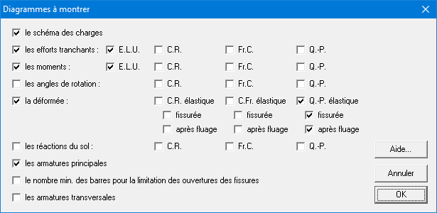
Parce que nous n’avons pas encore spécifié de diamètre pour les barres, le calcul des ouvertures des fissures ne peut se baser que sur les sections strictement nécessaires par le calcul. Par contre, l’ouverture d’une fissure est très dépendante des diamètres des barres et de leurs nombres; ce qui fait qu’il est impossible de calculer les ouvertures de fissures à partir des sections d’armature strictement requises par le calcul. C’est la raison pour laquelle ConCrete fait le calcul inverse: ConCrete vous calcule le nombre minimum des barres qui est nécessaire pour ne pas passer l’ouverture des fissures maximale, supposant que sur toute la longueur de la poutre la section réalisée est égale à la section strictement requise par le calcul et que toutes les barres ont le même diamètre.
