ConCrete can, besides the self-weight, also take nine different load groups into account. The properties of those load groups can be define din the dialog box below.
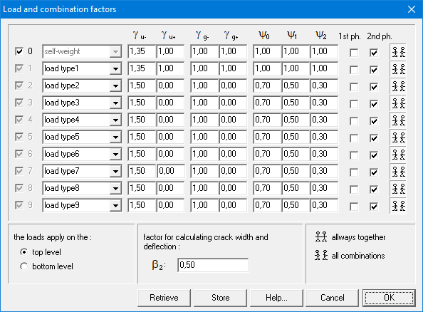
Let’s to trough the content of this dialog:
- Each load groups gets a name. Load type 0 is always the self-weight.
- Partial safety factors γ
The first two factors γu- and γu+ are safety coefficients for the ultimate limit state: the first one if the load has an unfavourable effect, the second one if the load has a favourable effect. In general, the Eurocode provides that the least favourable coefficient equals 1.35 for dead loads and the most favourable one equals 1.00; as for life loads, these coefficients equal 1.50 and 0.00 respectively. The next two coefficients γg- and γg+ are safety coefficients corresponding to the service limit state. In general, the Eurocode provides that the least favourable coefficient equals 1.00 for dead loads and the most favourable one also equals 1.00; as for life loads, these coefficients equal 1.00 and 0.00 respectively. - Combination factors Ψ
- Ψ0 is a combination coefficient which considers the fact that it is unlikely that multiple independent variable loads reach their maximum value at the same time.
- Ψ1 is a combination coefficient, which plays a role in the repeated occurrence of life loads. For buildings in general, will be taken equal to the value that can be exceeded during approximately 1% of the reference time.
- Ψ2 is a combination coefficient, which also plays a role in the repeated occurrence of life loads, but now the value for will be taken equal to the value that can be exceeded during at least 50% of the reference time.
More information on partial safety factors and combination factors can be found in standards. ConCrete used equation 6.10 (EN 1990) to generate the fundamental combinations in ultimate limit state (ULS FC).
- For each load group it is possible to indicate in which phase(s) the loads of this type are present. The first phase is calculated in an isostatic way (span by span), possibly with a reduced height (ho1 instead of ho). The required reinforcement for the ultimate limit state is calculated. Then, the beam is calculated in the second phase. In this phase, the beam is calculated in its hyperstatic condition, with the full height (ho). Again, the reinforcement for the ultimate limit state is calculated. The result for the ultimate limit state is the maximum of the first and second phase. Starting from this reinforcement, the stresses in the serviceability limit state in the concrete and in the reinforcement are calculated in the first phase (thus in an isostatic way and with reduced height). Then the increase of stresses in the second phase is determined. If the stresses are too high, the reinforcement is increased.
- Concrete will, by default, look at the loads in a load group span by span (
 is active by default). He will automatically apply a favourable or unfavourable factor to the spans to obtain the most unfavourable configuration (checkerboard pattern).
Yet, it’s possible some load groups (like self-weight and dead loads) don’t require this type of splitting up span by span. By setting the button active, you indicate that the loads from a certain load group should always be present or absent.
 - You can also determine whether the loads will act on the top or bottom level, this is of importance when determining the transverse reinforcement (cfr. classical truss girder analogy of Mörsch).
- The coefficient β2 is used to calculate the cracking width and the cracked deflection. Its value is 0,50 for sustained loads and 1,00 for short-term loading. The name β2 comes from an older standard ENV 1992. In EN 1992-1-1 is parameters is called β.
ConCrete kan behalve met het eigengewicht, ook rekening houden met negen andere lastengroepen. De eigenschappen van die lastengroepenkunnen ingesteld worden via onderstaand dialoogvenster.
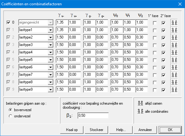
We overlopen hierna inhoud van dit venster.
- Elke lastengroep krijgt een naam. Lasttype 0 is steeds het eigengewicht.
- Partiële veiligheidscoëfficiënten γ:
De eerste 2 factoren γu- en γu+ zijn de veiligheidsfactoren op de belastingen in de uiterste grenstoestand. In de bruikbaarheidsgrenstoestand worden de karakteristieke waarden van de belastingen vermenigvuldigd met γg- en γg+. De coëfficiënten met een minteken worden toegepast wanneer de belasting een ongunstig effect heeft, de coëfficiënten met een plusteken in het geval de belasting een gunstig effect heeft. In het algemeen bedraagt de partiële factor voor de belastingen in de uiterste grenstoestand 1,35 voor vaste en 1,50 voor veranderlijke lasten met ongunstig effect. Bij gunstig effect worden deze waarden respectievelijk 1,00 en 0,00. In de gebruiksgrenstoestand worden alle partiële factoren, uitgezonderd de veranderlijke lasten met gunstig effect, gelijkgesteld aan 1,00. - Combinatiefactoren Ψ :
- Ψ0 is een combinatiecoëfficiënt die rekening houdt met het feit dat het weinig waarschijnlijk is dat meerdere onafhankelijke veranderlijke belastingen tezelfdertijd hun maximale waarde aannemen.
- Ψ1 is een combinatiecoëfficiënt die een rol speelt bij het herhaaldelijk optreden van veranderlijke belastingen. Voor gebouwen wordt zij in het algemeen gelijk genomen aan de waarde die gedurende ongeveer 1% van de referentietijd kan overschreden worden.
- Ψ2 is een combinatiecoëfficiënt die eveneens een rol speelt bij het herhaaldelijk optreden van veranderlijke belastingen, maar die ditmaal zodanig is gekozen dat ze gedurende minstens 50% van de referentietijd overschreden wordt.
Meer informatie over de waarden van de partiële veiligheidscoëfficiënten γ en combinatiefactoren Ψ kan u vinden in de norm. ConCrete gebruikt vergelijking 6.10 (zie EN 1990) om de fundamentele combinaties in uiterste grenstoestand (UGT FC) te maken.
- Voor elke lastengroep kan opgegeven worden in welke fase(s) de lasten die ertoe behoren aanwezig zijn. De eerste fase wordt isostatisch uitgerekend (overspanning per overspanning) met een eventueel kleinere doorsnede (hoogte ho1 i.p.v. ho). In uiterste grenstoestand wordt de benodigde wapening berekend. Vervolgens wordt de balk in tweede fase In deze fase wordt de balk hyperstatisch uitgerekend zoals hij ingegeven werd, met de volledige doorsnede (hoogte ho). De wapening wordt opnieuw bepaald in de uiterste grenstoestand. Het uiteindelijk resultaat in de uiterste grenstoestand is het maximum van de eerste en van de tweede fase. Vertrekkend van deze wapening, worden in de gebruiksgrenstoestand de spanningen in het beton en de wapening berekend in de eerste fase (dus isostatisch en met kleinere hoogte). Vervolgens wordt de toename van de spanningen bepaald in de tweede fase. Zijn de betonspanningen te groot, dan wordt de wapening vergroot.
- ConCrete zal standaard de lasten uit de betreffende lastengroep steeds als per overspanning behandelen ( is default actief). ConCrete zal automatisch bepaalde velden belasten met een gunstige factor en andere met een ongunstige factor om zo te komen tot de meest nadelige belastingssituatie (dambordpatroon).
Het kan echter zijn dat voor sommige belastingen (zoals eigengewicht en permanente lasten) dat deze opsplitsing in gunstig belaste en ongunstig belaste velden irrelevant is. Door de knop actief te zeggen, wordt aangegeven dat lasten uit de desbetreffende lastengroep altijd samen aanwezig of afwezig zijn. - Er kan ook opgegeven worden of de belastingen op de boven- of op de ondervezel aangrijpen, wat van belang is bij de bepaling van de dwarskrachtwapening (zie dit artikel).
- De coëfficiënt β2 wordt gebruikt voor de berekening van de scheurwijdte en de doorbuiging. Hij bedraagt 0.50 voor langdurige en/of herhaalde belastingen en 1.00 voor éénmalige, kortstondige belastingen. De naamgeving β2 is afkomstig uit de voornorm ENV 1992. In EN 1992-1-1 heet deze parameter β.
En plus du poids propre, ConCrete peut également prendre en compte neuf autres types de charges (syn. : groupes de charges). Les propriétés de ces groupes de charges peuvent être définies via la boîte de dialogue ci-dessous.
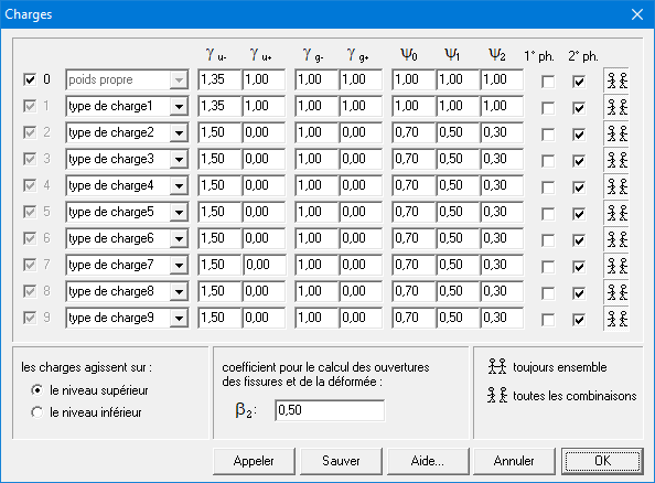
Nous allons maintenant passer en revue le contenu de cette fenêtre.
- Chaque groupe de charges reçoit un nom. Le Type de charge 0 est toujours le propre poids.
- Les coefficients de sécurité γ:
Les deux premiers facteurs γu- et γu+ sont les coefficients de sécurité pour l’état-limite ultime : la première dans le cas où la charge a un effet défavorable, la seconde dans le cas où la charge a un effet favorable. En général, l’Eurocode prévoit que le coefficient le plus défavorable est égal à 1.35 pour les charges permanentes et que le plus favorable est égal à 1.00; pour les charges utiles, ces coefficients sont respectivement de 1.50 et 0.00. Les deux coefficients suivants γg- et γg+ sont les coefficients de sécurité correspondant à l’état-limite de service. En général, l’Eurocode prévoit que le coefficient le plus défavorable est égal à 1.00 pour les charges permanentes et que le plus favorable est également de 1.00; pour les charges utiles, ces coefficients sont respectivement de 1.00 et 0.00. - Les coefficients de combinaison Ψ :
- Ψ0 est le coefficient de combinaison avec lequel ce type de charge est appliqué lors du calcul en état-limite ultime (combinaison fondamentale) et dans les combinaisons rares en état-limite de service quand c’est une autre surcharge qui est la plus défavorable.
- Ψ1 est le coefficient de combinaison quand ce type de charge est appliqué lors du calcul dans la combinaison accidentelle dans l’état-limite ultime et dans la combinaison fréquente en état-limite de service quand cette surcharge est la plus défavorable.
- Ψ2 est le coefficient de combinaison avec lequel on applique ce type de charge lors du calcul dans la combinaison quasi-permanente en état-limite de service. Dans la combinaison accidentelle en état-limite ultime et dans la combinaison fréquente en état-limite de service, ce coefficient est appliqué quand c’est une autre surcharge qui est la plus défavorable.
Plus d’informations sur les valeurs coefficients de sécurité γ et coefficients de combinaison Ψ peuvent être trouvées dans la norme. ConCrete utilise l’équation 6.10 (voir EN 1990) pour générer les combinaisons fondamentales à l’état limite ultime (ELU FC).
- Pour chaque type de charge, nous pouvons indiquer dans quelle(s) phase(s) ce type est présent. La première phase est calculée de manière isostatique (portée par portée) avec une section éventuellement réduite (hauteur ho1 au lieu de ho). L’armature nécessaire à l’état limite ultime est calculée. Puis, la poutre est calculée dans la deuxième phase. Dans cette phase, la poutre est calculée de manière hyperstatique, comme elle était introduite, avec la section totale (hauteur ho). De nouveau, l’armature nécessaire pour l’état limite ultime est calculée. Enfin, le résultat finale pour l’état limite ultime est le maximum des résultats des deux phases. A partir de l’armature résultante, les contraintes du béton et de l’acier sont calculées dans l’état limite de service dans la première phase (donc isostatique et avec hauteur réduite). Ensuite, le logiciel détermine l’augmentation des contraintes dans la deuxième phase. Si les contraintes sont trop grandes, les quantités d’armature seront augmentées.
- Par défaut, ConCrete traitera toujours les charges du groupe de charge concerné par travée (active par défaut). Il chargera automatiquement certains portées avec un facteur favorable et d’autres avec un facteur défavorable afin d’arriver à la situation de charge la plus défavorable.
Cependant, c’est possible que pour certaines groupes de charges (comme le poids propre et les charges permanentes), cette division n’est pas pertinente. Avec le bouton actif, il est indiqué que les charges du groupe de charges respectif sont toujours présentes ou absentes ensemble. - Cette fenêtre de dialogue vous permet de spécifier si les charges agissent sur le niveau supérieur ou inférieur, ce qui peut s’avérer capital lors de la détermination de l’armature transversale (cfr. cet article).
- Le coefficient β2 pour le calcul des ouvertures des et de la déformée est normalement égale à 0.50 pour des charges de longue durée et/ou répétitives et à 1.00 pour des charges uniques et momentanées.
