Material properties and safety factors
The material characteristics necessary for checking steel/timber are defined as soon as you have selected the steel or timber quality when designing elements.
In addition to the strength properties, 1•2•Build also uses partial safety factors (according to Eurocode). The values for the safety factors are included in the calculation note if you have calculated elements in steel or timber with 1•2•Build.
Resistance check
The resistance check verifies that the calculated internal forces do not exceed the limits imposed by the standard. Different checks are performed according to Eurocode (EN1993-1-1), namely those listed below. 1•2•Build performs these verifications for all combinations in ultimate limit state.
- Axial tension (§6.2.3)
- Axial compression (§6.2.4)
- Bending My’ (§6.2.5)
- Bending Mz’ (§6.2.5)
- Shear force Vz’ (§6.2.6)
- Shear force Vy’ (§6.2.6)
- Torsion Mx’ (§6.2.7)
- Bending My’ and shear force Vz’ (§6.2.8)
- Bending Mz’ and shear force Vy’ (§6.2.8)
- Double bending and axial force (§6.2.9)
- Double bending with axial force and shear force (§6.2.10)
To view the result of the strength verification, you click on the button![]() in the icon pallet. The result is always expressed as a percentage of the total capacity of the bar against the considered loads. For more details, double click a bar:
in the icon pallet. The result is always expressed as a percentage of the total capacity of the bar against the considered loads. For more details, double click a bar:
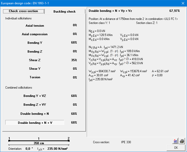
This dialog summarizes all the performed checks. The check that resulted in the highest percentage is shown in bold. For this check, the intermediate results are shown on the right.
To view the details of the other checks, click on the line containing the check with its percentage.
Stability check
The stability check verifies that the calculated internal forces do not cause buckling or lateral torsional buckling. Different checks are performed according to Eurocode, namely those in the table below. 1•2•Build performs these verifications for all combinations in ultimate limit state.
- Buckling around the strong axis (§6.3.1)
- Buckling around the weak axis (§6.3.1)
- Torsional buckling (§6.3.1)
- Lateral torsional buckling (§6.3.2)
- Buckling around the strong axis due to My’, Mz’ and N (§6.3.3)
- Buckling around the weak axis due to My’, Mz’ and N (§6.3.3)
To view the result of the stability verification, you click on the button ![]() in the icon pallet. The result is always expressed as a percentage of the total capacity of the bar against the considered loads. For more details, double click a bar:
in the icon pallet. The result is always expressed as a percentage of the total capacity of the bar against the considered loads. For more details, double click a bar:
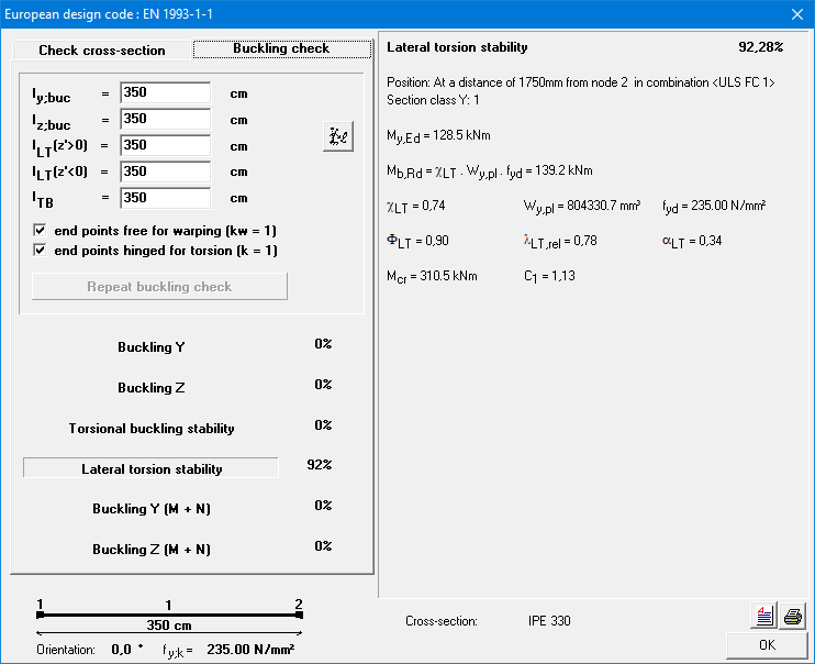
This dialog summarizes all the performed checks. The check that resulted in the highest percentage is shown in bold. For this check, the intermediate results are shown on the right.
To view the details of the other checks, click on the line containing the check with its percentage.
At the top left of this window, there are some other important parameters for the stability control:
- ly,buc and lz,buc are the buckling lengths about the strong and weak axis, respectively. They are automatically calculated by 1•2•Build, but you can always change the value by clicking in the appropriate field or by clicking the button
 .
. - lLT (z’ > 0) and lLT (z’ < 0) are the lateral torsional buckling lengths at the top flange and at the bottom flange respectively. Depending on the sign of the bending moment My’ either the bottom or the top of the bar can be under compression. That is why 1•2•Build allows to assume a different lateral torsional buckling lengths for the top and bottom.
- k and kw are factors that take the effect of the different types of boundary conditions on the elastic cricital moment Mcr into account.
1•2•Build assumes a safe value, but you can always change it.- k is equal to 1 if the lateral deflection is not prevented at either support point. Otherwise, it is assumed that both end points allow rotation around the weak axis of the profile (k = 0,5).
- kw takes into account whether the cross-sections at the ends are prevented from warping. kw=1 is recommended unless special provisions are made.
From the moment you change one of the parameters above, you need to redo the stability verification by clicking on the button ‘Recalculate buckling risk’.
Materiaaleigenschappen en veiligheidsfactoren
De noodzakelijke materiaal karakteristieken voor een staal-/ houtcontrole, zijn bepaald zodra u bij de dimensionering van elementen een staal- of houtkwaliteit kiest.
Naast de sterkte-eigenschappen, gebruikt 1•2•Build ook nog partiële veiligheidsfactoren (conform Eurocode). De ingestelde waarden voor de veiligheidsfactoren worden opgenomen in de berekeningsnota als u elementen in staal of hout hebt berekend met 1•2•Build.
Weerstandscontrole
De controle van de weerstand kijkt na of de berekende snedekrachten de door de norm opgelegde grenzen niet overschrijden. Er worden diverse controles uitgevoerd conform Eurocode, namelijk diegene opgesomd in onderstaande lijst. 1•2•Build voert deze controles uit voor alle combinaties in uiterste grenstoestand.
- Axiale trek (§6.2.3)
- Axiale druk (§6.2.4)
- Buiging My’ (§6.2.5)
- Buiging Mz’ (§6.2.5)
- Dwarskracht Vz’ (§6.2.6)
- Dwarskracht Vy’ (§6.2.6)
- Torsie Mx’ (§6.2.7)
- Buiging My’ en dwarskracht Vz’ (§6.2.8)
- Buiging Mz’ en dwarskracht Vy’ (§6.2.8)
- Dubbele buiging met normaalkracht (§6.2.9)
- Dubbele buiging met normaalkracht en dwarskracht (§6.2.10)
Om de resultaten van de weerstandscontrole te bekijken, klikt u op de knop ![]() in het iconenpalet. Het resultaat wordt steeds uitgedrukt in procenten van de maximale weerstand van de staaf tegen de beschouwde sollicitatie. Voor meer details over de berekening van een bepaalde staaf, dubbelklik een staaf:
in het iconenpalet. Het resultaat wordt steeds uitgedrukt in procenten van de maximale weerstand van de staaf tegen de beschouwde sollicitatie. Voor meer details over de berekening van een bepaalde staaf, dubbelklik een staaf:

Dit dialoogvenster vat alle uitgevoerde controles samen. De controle die voor het hoogste percentage zorgt, wordt in het vet voorgesteld. Voor deze controle, worden aan de rechterkant de tussenresultaten getoond.
Om de details van de andere controles te bekijken, klikt u op de lijn waar de controle met het bijbehorende percentage staat.
Stabiliteitscontrole
De stabiliteitscontrole kijkt na of de berekende snedekrachten geen knik of kip veroorzaken. Er worden diverse controles uitgevoerd conform Eurocode, namelijk diegene opgesomd in onderstaande lijst. 1•2•Build voert deze controles uit voor alle combinaties in uiterste grenstoestand.
- Buigingsknik om de sterke as (§6.3.1)
- Buigingsknik om de zwakke as (§6.3.1)
- Torsieknik of ruimtelijke knik (§6.3.1)
- Laterale torsieknik (§6.3.2)
- Knik om de sterke as t.g.v. My’, Mz’ en N (§6.3.3)
- Knik om de zwakke as t.g.v. My’, Mz’ en N (§6.3.3)
Om de resultaten van de weerstandscontrole te bekijken, klikt u op de knop ![]() in het iconenpalet. Het resultaat wordt steeds uitgedrukt in procenten van de maximale weerstand van de staaf tegen de beschouwde sollicitatie. Voor meer details over de berekening van een bepaalde staaf, dubbelklik een staaf:
in het iconenpalet. Het resultaat wordt steeds uitgedrukt in procenten van de maximale weerstand van de staaf tegen de beschouwde sollicitatie. Voor meer details over de berekening van een bepaalde staaf, dubbelklik een staaf:
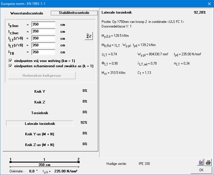
Dit dialoogvenster vat alle uitgevoerde controles samen. De controle die voor het hoogste percentage zorgt, wordt in het vet voorgesteld. Voor deze controle, worden aan de rechterkant de tussenresultaten getoond.
Om de details van de andere controles te bekijken, klikt u op de lijn waar de controle met het bijbehorende percentage staat.
Links bovenaan dit venster staan nog enkele belangrijke parameters voor de stabiliteitscontrole:
- ly,buc en lz,buc zijn de kniklengtes om de respectievelijk de sterke en zwakke as. Ze worden automatisch berekent door 1•2•Build, maar u kan de waarde altijd aanpassen door in het desbetreffende veld te klikken of via de knop .
- lLT (z’ > 0) en lLT (z’ < 0) zijn de kiplengtes respectievelijk aan de bovenflens en aan de onderflens. Afhankelijk van het teken van het buigend moment My’ kan ofwel de onderzijde ofwel de bovenzijde worden gedrukt. Vandaar dat 1•2•Build toelaat een verschillende kiplengte aan te nemen voor de bovenzijde en onderzijde van de staaf.
- k en kw zijn factoren die het effect van de verschillende types randvoorwaarden op het theoretisch elastisch kipmoment Mcr in rekening brengen (enkel zichtbaar voor staal).
1•2•Build neemt een veilige waarde aan, maar u kan die altijd aanpassen.- is gelijk aan 1 indien de zijdelingse uitbuiging aan geen van beide oplegpunten wordt belemmerd. In het andere geval wordt aangenomen dat beide eindpunten een rotatie toelaten omheen de zwakke as van het profiel (k = 0,5).
- kw houdt rekening met het feit of de doorsneden aan de uiteinden worden verhinderd van welving. kw=1 wordt aanbevolen, tenzij speciale voorzieningen worden getroffen.
Van het ogenblik u één van bovenstaande parameters wijzigt, dient u de stabiliteitscontrole te hernemen door te klikken op de knop ‘Herbereken knikgevaar’.
Propriétés des matériaux et facteurs de sécurité
Les propriétés des matériaux nécessaires pour la vérification acier/bois sont fixées dès que vous sélectionnez la qualité acier/ bois pendant le dimensionnement des éléments.
En plus ces propriétés de résistance, 1•2•Build utilise également des facteurs de sécurité partiels (selon Eurocode). Les valeurs définies pour les facteurs de sécurité sont incluses dans la note de calcul si vous avez calculé des éléments en acier ou en bois avec 1•2•Build.
Vérification de résistance
Le contrôle de résistance vérifie que les efforts internes calculés ne dépassent pas les limites imposées par la norme. Différents contrôles sont effectués selon l’Eurocode, à savoir ceux du tableau ci-dessous. 1•2•Build effectue ces vérifications pour toutes les combinaisons à l’état limite ultime.
- Effort normal en traction (§6.2.3)
- Effort normal en compression (§6.2.4)
- Moment My’ (§6.2.5)
- Moment Mz’ (§6.2.5)
- Effort tranchant Vz’ (§6.2.6)
- Effort tranchant Vy’ (§6.2.6)
- Torsion Mx’ (§6.2.7)
- Moment My’ et effort tranchant Vz’ (§6.2.8)
- Moment Mz’ et effort tranchant Vy’ (§6.2.8)
- Moment My’ et Mz’ avec effort normal (§6.2.9)
- Moment My’ et Mz’ avec effort normal et effort tranchant (§6.2.10)
Pour afficher le résultat de la vérification de la résistance, vous cliquez sur le bouton ![]() dans la palette d’icônes. Le résultat est toujours exprimé en pourcentage de la capacité totale de la barre par rapport aux charges considérées. Pour plus de détails, double-cliquez sur une barre:
dans la palette d’icônes. Le résultat est toujours exprimé en pourcentage de la capacité totale de la barre par rapport aux charges considérées. Pour plus de détails, double-cliquez sur une barre:
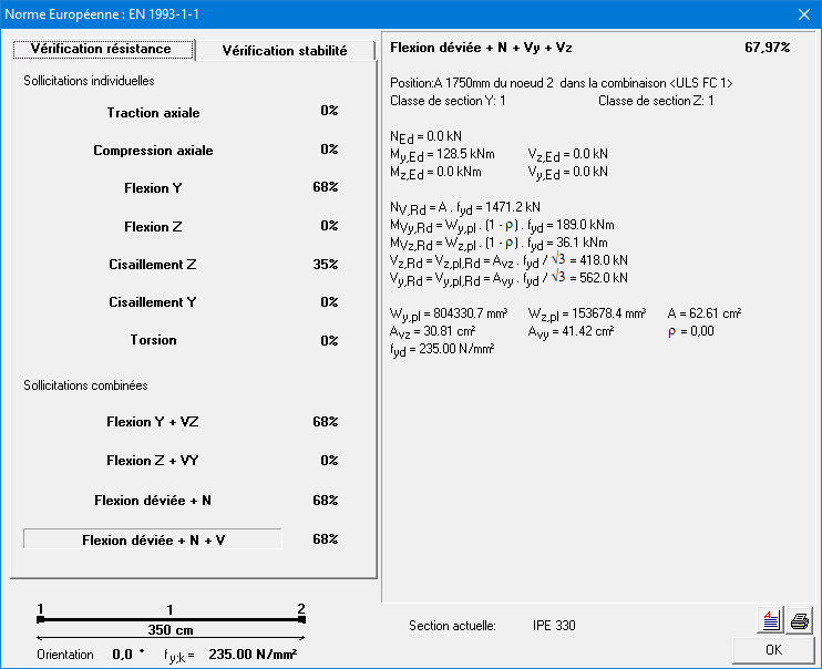
Cette boîte de dialogue récapitule toutes les vérifications effectuées. Le contrôle qui produit le pourcentage le plus élevé est affiché en gras. Pour ce contrôle, les résultats intermédiaires sont affichés à droite.
Pour obtenir le détail de calcul, cliquez la ligne avec la vérification qui vous intéresse.
Vérification de la stabilité
Le contrôle de stabilité vérifie que les efforts internes calculés ne provoquent pas de flambement ou de déversement. Différents contrôles sont effectués selon l’Eurocode, à savoir ceux du tableau ci-dessous. 1•2•Build effectue ces vérifications pour toutes les combinaisons à l’état limite ultime.
- flambement autour de l’axe fort (§6.3.1)
- flambement autour de l’axe faible (§6.3.1)
- torsion flambement (§6.3.1)
- déversement (§6.3.2)
- effort normal, moment et flambement (§6.3.3)
- effort normal, moment et déversement (§6.3.3)
Pour afficher le résultat de la stabilité, vous cliquez sur le bouton ![]() dans la palette d’icônes. Le résultat est toujours exprimé en pourcentage de la capacité totale de la barre par rapport aux charges considérées. Pour plus de détails, double-cliquez sur une barre :
dans la palette d’icônes. Le résultat est toujours exprimé en pourcentage de la capacité totale de la barre par rapport aux charges considérées. Pour plus de détails, double-cliquez sur une barre :
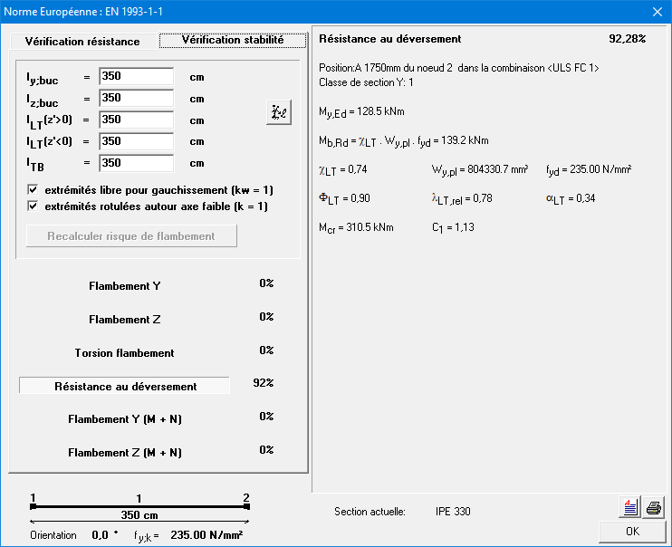
Cette boîte de dialogue récapitule toutes les vérifications effectuées. Le contrôle qui produit le pourcentage le plus élevé est affiché en gras. Pour ce contrôle, les résultats intermédiaires sont affichés à droite.
Pour obtenir le détail de calcul, cliquez la ligne avec la vérification qui vous intéresse.
Cette fenêtre de dialogue contient aussi des paramètres utilisés dans la vérification:
- ly,buc et lz,buc sont les longueurs de flambement autour de l’axe fort et faible, respectivement. Ils sont automatiquement calculés par 1•2•Build, mais vous pouvez toujours modifier la valeur en cliquant dans le champ approprié ou en cliquant sur le bouton .
- lLT (z’ > 0) et lLT (z’ < 0) sont les longueurs de déversement a la semelle supérieure et inférieure respectivement. Selon le signe du moment de flexion My’, le bas ou le haut du profile peut être pressé. C’est pourquoi 1•2•Build permet de supposer une longueur de déversement différente pour le haut et le bas de la barre.
- k et kw sont des facteurs qui prennent en compte l’effet des différents types de supports aux limites sur le moment critique Mcr.
1•2•Build suppose une valeur sûre, mais vous pouvez toujours la modifier.- Si le support utilisé n’a pas de résistance significative pour empêcher la rotation de la section autour de son axe, il faut garder la case cochée pour ‘extrémités rotulées autour axe long (k = 1)’. Sinon, on suppose que les deux extrémités permettent une rotation autour de l’axe faible du profil (k=0,5).
- De même, si le support utilisé ne permet pas d’empêcher le gauchissement de la section à son extrémité, il faut aussi cocher ‘extrémité libre pour gauchissement (kw = 1).
Dès que vous modifiez l’un des paramètres ci-dessus, vous devez reprendre le contrôle de stabilité en cliquant sur le bouton ‘Recalculer risque flambement’.
