The buckling strength of a concrete, steel or timber member depends on the buckling length. The buckling length depends on
- the system length
- the end conditions at the start and endpoint of the member. These end conditions can be supports
 or an adjacent structure
  .
.
The default assigned buckling lengths depend on how you’ve down the structure:
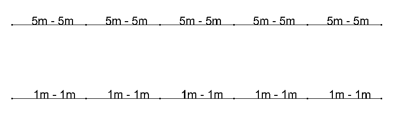
- If you draw a line of 5m and divide it in 5, each part will have a buckling length of 5m in both directions.
- If you draw 5 lines of 1m, each line will have a buckling length of 1m in both directions.
For some members this will be a safe assumption, for others not. Thus leaving the buckling lengths on their default value is not an option. The end-user must impose the correct buckling lengths. This can be done two ways:
- either impose them manually.
- either let Diamonds calculate them.
Manually impose the buckling lengths
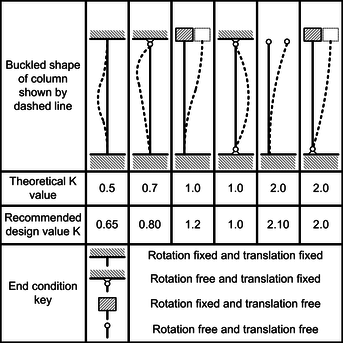
- Determine the buckling lengths using tables, graphs, diagrams, … These tables, graphs, diagrams offer a solution for simple support conditions . More supportcondition like are usually not mentioned or require a lot of calculation work.
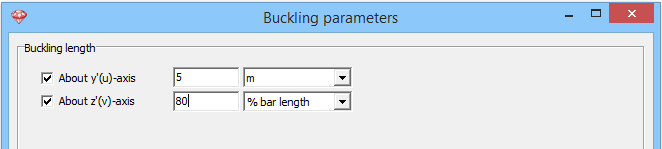
- Select the bar(s) for which you want to impose the buckling lengths.
- Click on
 and enter the desired buckling lengths in meter or a percentage for the bar length.
Let Diamonds calculate the buckling lengths
As mentioned, the buckling lengths depend on the system length and the end conditions. Since members have to ‘be split’ in order to create a node in Diamonds, the system length and accompanying end conditions are not unequivocally determined. It’s also possible that a certain member is not capable of acting as a buckling support (for example: it is doubtful that a slim L-section will prevent a heavy HEM from buckling).
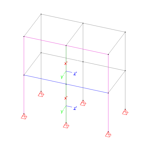
For example in the portch below all bars have a length L. We focus on the green column and consider buckling around the y’-axis.
- bars 1 and 2 can be seen as continuous. The system length is 2*L.
- bars 1 and 2 can be seen as discontinuous. The system length equals L. Also different end conditions will apply then when they’re condisered as one continuous bar.
By definining buckling groups, the system length and accompanying end conditions are not unequivocally determined. Thus if, you calculate the buckling lengths without defining the groups first, you’ll have no clue what comes out of the buckling length calculations (and the resulting design verification)!
Define the groups for buckling
As an example, we’ll define the groups for the green column:
- Go to the Geometry configuration
 .
. - Turn on the local coordinate system for bars
 . The size of the local coordinate system and fonts can be changed on the right side in the pallet ‘size’.
 - Take a solid representation
 .
. - Select ‘buckling around the y’-axis’ in the pallet ‘Show groups’.
- Using the corkscrew rule along the y’-axis, the buckling direction of the green columns is to the left or the right. Assuming the blue beams work as a buckling support, both columns have to be ungrouped.
- Select the green columns and click on
 .
. - Select ‘buckling around the z’-axis’ in the pallet ‘Show groups’.
- Using the corkscrew rule along the z’-axis, the buckling direction of the green columns is to the front or back. There’s nothing blocking the buckling in that direction, both columns have to be grouped.
- Select the green columns and click on
 .
. - Repeat this proces for all bars (columns and beams) in both the y’ and z’ direction!
Perform the calculation of the buckling lengths
- Click on
 to calculate the buckling lengths.
 - Click on to see the calculated buckling length.
