In order to explain how the module Moving Loads works, we model the train below. The dimensions of the train and its loads are given. The shape of the trajectory is drawn in step 1 (see further). There’s a bumper at both ends of the trajectory. 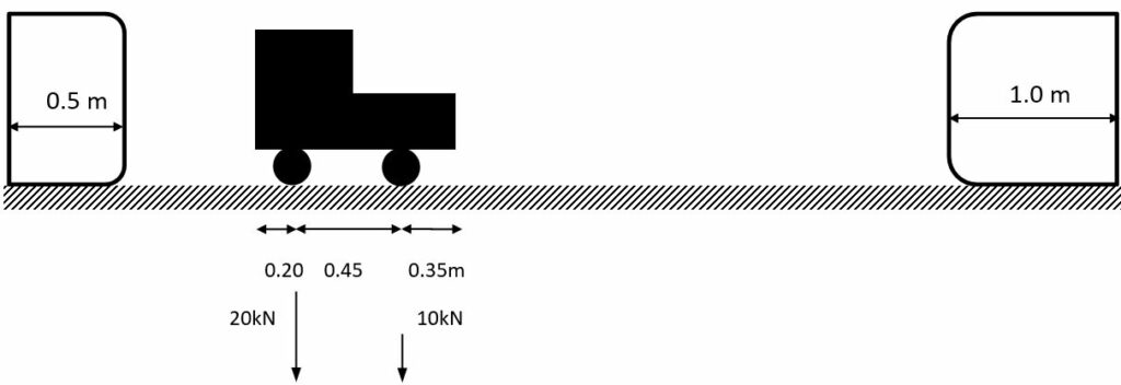
In Diamonds
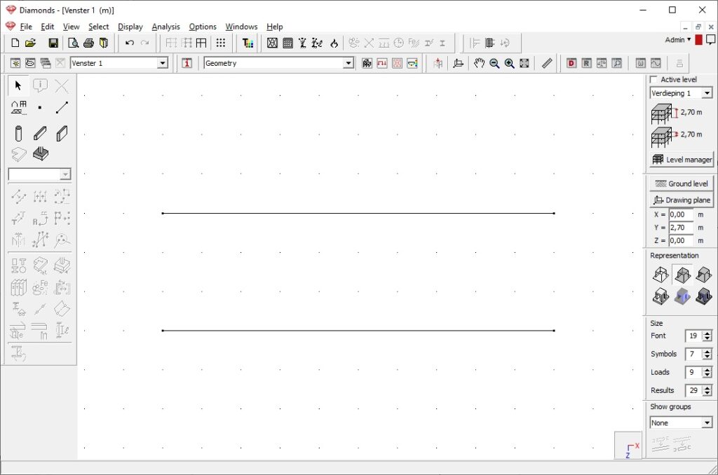
- Define the trajectory (= lines or bar) of the moving load in the Geometry configuration
 .
.
If you want to apply a moving load on a plate, you must draw the trajectory in the surface of the plate.
In the image below, two trajectories are drawn. One trajectory is slightly shorter than the other one.
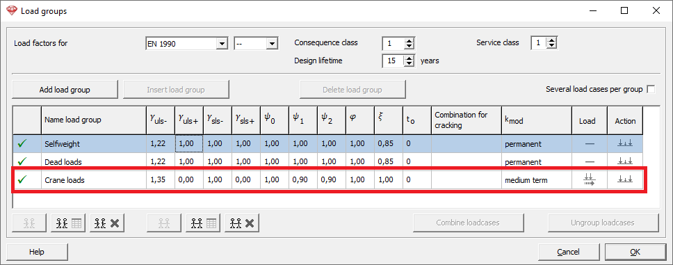
- Define a load group for moving loads
- Go to the loads configuration
 and click on
  .
. - Add a new load group. Set the type to Crane loads.
- Go to the loads configuration
- Add the moving load to the library.
- Select the load group Crane loads from the pull down list and click on
 .
. - Click New and enter the properties of the moving load.
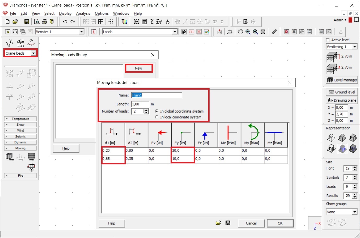
- Select the load group Crane loads from the pull down list and click on
- Allocate the moving load to the trajectory.
- Select the trajectory and click on
 . The moving load Train1 we just defined, is automatically selected from the pull downlist.
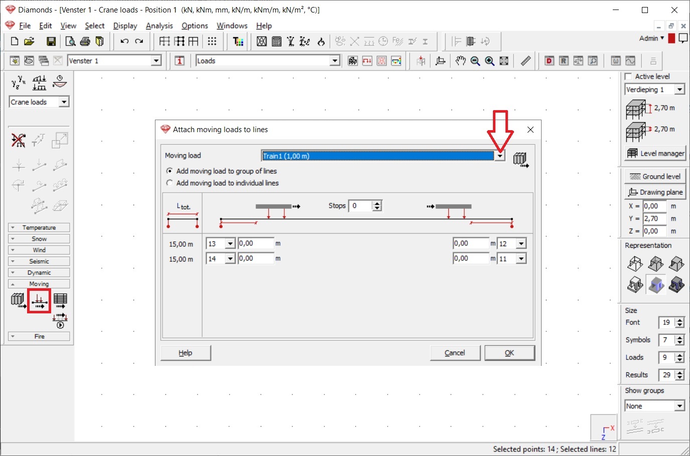
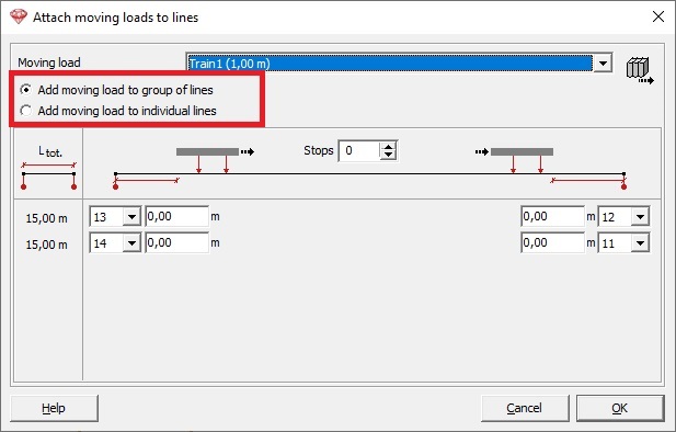
- Choose whether you wish to apply the crane load to the group of lines or to the individual lines. In this case we choose group of lines.
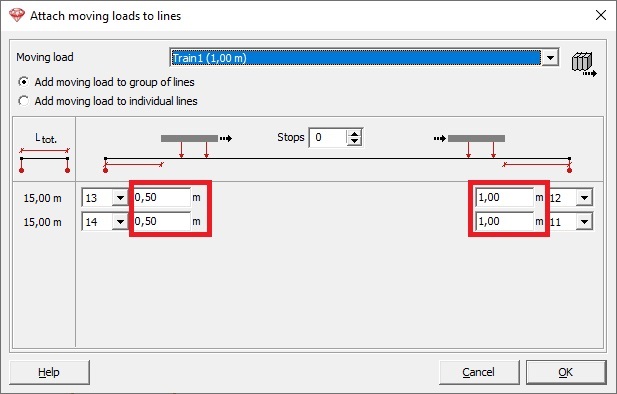
- Enter the dimensions of the bumpers.
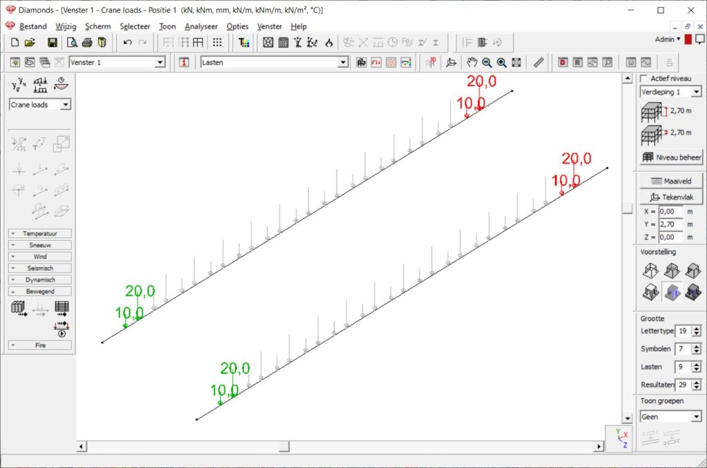
- Click OK to close the dialog. You will see a graphic illustration of the moving load.
Green is were the moving load start, red is were it ends.
- Select the trajectory and click on
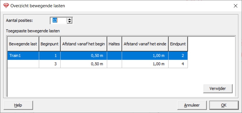
- Click on
 to get a summary of all applied moving loads.
- Click on
 to start/ stop the animation of the moving load.
Notes:
- Diamonds shows the enveloppe result from all the positions of the train. Not the results for each position separately. Therefor this feature cannot be used to create influence lines.
- When importing a Diamonds model with moving loads into PowerFrame, it is advised to redefine the moving loads again in PowerFrame and visa versa.
