Description

| Geometry | Plate section for points A, B: | Preslabs  |
|---|---|---|
| Plate section for point C: | Two way slab |
|
| Material: | C25/30 | |
| Concrete cover: |  |
|
| Internal forces | Point A: |    |
| Point B: |    |
|
| Point C: |    |
|
| Standard | EN 1992-1-1 [- -] |
Independent reference results
Mesh points and interpolation
Diamonds calculates the reinforcement at each vertex and in the centre of each triangle side of a mesh triangle. The ‘attractive’ colour gradient of the results is created by interpolation.
To avoid having to worry about interpolation here as well, we specifically take internal forces that occur in mesh nodes.
You can easily retrieve the internal forces in the mesh nodes via the results table ![]() . Or if you add a point in the geometry, like we did for point C, that becomes a meshnode by default.
. Or if you add a point in the geometry, like we did for point C, that becomes a meshnode by default.
Diamonds sign convention
Diamonds calculates the bending moments Mxx, Mzz and the torsional moment Mxz in the plate. When calculating the reinforcement, the contribution of the torsional moment Mxz cannot be ignored. Therefor Mxx and Mzz are not the reinforcement moments ( = the moments based on with the reinforcement is calculated). Instead Diamonds uses Wood-Armer moments to calculate the reinforcement. They are listed in the table below.
| Bottom | Top | ||
|---|---|---|---|
  |
  |
||
If  : : |
  |
If  : : |
 |
If  : : |
  |
If  : : |
 |
The sign convention for Wood-Armer moments is:
- Positive moment causes sagging ⌣ (tension in the bottom)
- Negative moment causes hogging ⌢ (tension in the top)
That is the opposite of the sign convention in Diamonds. As a result, the headers “Bottom” and “Top” should be switched when we want to recalculate Diamonds.
| Top | Bottom | ||
|---|---|---|---|
|
|
||
| If : |
|
If : |
|
| If : |
|
If : |
|
Diamonds nomenclature
In Diamonds, the x’-direction is the principal direction of the plate and the z’-direction the secundairy (= local coordinate system of a surface). Also in Diamonds, top is referred to as “Superior” and bottom as “Inferior”. Let’s convert the table again to take these modifications into account.
| Top (Superior) | Bottom (Inferior) | ||
|---|---|---|---|
  |
  |
||
If  : : |
  |
If  : : |
  |
If  : : |
  |
If  : : |
  |
 is thus the reinforcement moment to calculate the top reinforcement parallel to the local z’-axis of the plate.
 is the reinforcement moment to calculate the bottom reinforcement parallel to the local z’-axis.
Determine the reinforcement moments
| Point |  |
|
 |
|
|---|---|---|---|---|
| A | -0.09+|16.61|=16.52 | -0.86+|16.61|=15.75 | -0.09-|16.61|=-16.70 | -0.86-|16.61|=-17.47 |
| B | 67.81+|-0.05|=67.86 | 24.41+|-0.05|=24.46 | 67.81-|-0.05|=67.76 | 24.41-|-0.05|=24.36 |
| Because both and > 0, their value is changed to 0. |
||||
| C | -14.17+|-0.26|=-13.91 | -0.01+|-0.26|=0.25 | -14.17-|-0.26|=-14.43 | -0.01-|-0.26|=-0.27 |
Because < 0, and  |
||||
Reinforcement calculation
- Based on the names Mxs, Mzs, Mxi, Mzi we know where the reinforcement is going to be placed. Therefor we’re neglecting the signs of the reinforcement moments in the table below.
- To calculate the reinforcement in a plate in bending, we use the same formulae as for a beam (see DC EC 02), but with
 equal to 1m. We repeat the process from DC EC 02 for of point A. The principle is the same for the other reinforcement moments.
![\[d=h-c=180mm-35mm=145mm\]](https://support.buildsoft.eu/wp-content/ql-cache/quicklatex.com-f76db359b1a591dedd3670a09f529524_l3.png "Rendered by QuickLaTeX.com")
![\[\mu _d=\frac{M_{xs}}{b\cdot d^2\cdot f_{cd}}=\frac{16.52\text{kNm}}{1000mm\cdot (145mm)^2\cdot 16.7\text{MPa}}=0.005\]](https://support.buildsoft.eu/wp-content/ql-cache/quicklatex.com-8d51f1bb3b7097b58511424bcfc78727_l3.png "Rendered by QuickLaTeX.com")
Table 3 from Gewapend beton: numeri (click here to open the Table) shows
 as a function of
  , and we find:
![\[\omega _1=0.005\]](https://support.buildsoft.eu/wp-content/ql-cache/quicklatex.com-8e93f6390df35ddaab3165d5506f2aea_l3.png "Rendered by QuickLaTeX.com")
![\[A_{s1}=\omega _1 \cdot b\cdot d\cdot \frac{f_{cd}}{f_{yd}}=0.005 \cdot 145mm \cdot 1000mm \cdot \frac{16.7\text{MPa}}{434.8\text{MPa}}=272mm^2\]](https://support.buildsoft.eu/wp-content/ql-cache/quicklatex.com-9972b451ae0ae559a731ebceb403fea0_l3.png "Rendered by QuickLaTeX.com")
However, pay attention when calculating
 in points A & B. The plate is a preslab. The useful height for the secundairy top reinforcement is measured starting from the top of the preslab d= h-(4)
 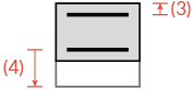 (more info).
| Results | Reinforcement moments [kNm] |
Usefull height  [mm] [mm] |
Reinforcement amount [mm²] |
|---|---|---|---|
| Point A |  |
145 | 272 |
 |
= 180 – 50 – 35= 9 | 407 | |
 |
145 | 275 | |
 |
145 | 288 | |
| Point B |  |
145 | 1212 |
 |
= 180 – 50 – 35= 95 | 653 | |
|
145 | 0 | |
|
145 | 0 | |
| Point C |  |
115 | 0 |
|
115 | 0 | |
 |
115 | 302 | |
 |
115 | 5 |
Diamonds results and comparison

Longitudinal upper reinforcement calculated by Diamonds in Point B (EN 1992-1-1 [- -])
Diamonds calculates the reinforcement required for the ULS. When the SLS requires additional reinforcement, it will be added to the ULS amount and named ‘TOT’. So when comparing results for this validation examole, look at the ULS.
| Results | Independent reference | Diamonds | Difference | |
|---|---|---|---|---|
| Point A |  |
272 mm² | 273 mm² | ≈0% |
|
407 mm² | 407 mm² | 0% | |
 |
275 mm² | 276 mm² | ≈0% | |
 |
288 mm² | 289 mm² | ≈0% | |
| Point B | |
1212 mm² | 1214 mm² | ≈0% |
|
653 mm² | 653 mm² | 0% | |
|
0 mm² | 0 mm² | 0% | |
|
0 mm² | 0 mm² | 0% | |
| Point C | |
0 mm² | 0 mm² | 0% |
|
0 mm² | 0 mm² | 0% | |
|
302 mm² | 303 mm² | ≈0% | |
|
5 mm² | 6 mm² | ≈0% | |
References
- EN 1992-1-1: 2005 + AC: 2010
- Van Hooymissen, L., Spegelaere, M., Van Gysel, A., & De Vylder, W. (2002). Gewapend beton. Academia Press
Keep in mind that the calculations in this book are made done using the NBN B15-002/ ENV 1992-1. Both old standards. However, this book still remains a good reference if you want to understand how reinforcement calculations work. - Gruyaert, E., & Minne, P. (2019). Gewapend beton: numeri.
This reference is a summary of Gewapend beton (2002) but with updated formula and principles according to EN 1992-1-1. This document contains multiple graphs and tables helping the design of reinforced concrete. - R. H. WOOD, The reinforcement of slabs in accordance with a pre-determined fiel of moments (original paper), Concrete magazine February 1968
- Tested in Diamonds 2026.
