Description

| Material | Modulus of elasticity |  |
|---|---|---|
| Thermal dilation |  |
|
| Geometry | Cross-section | IPE 500 |
| Boundary conditions | Case 1: cantilever | |
| Case 2: fixed beam | ||
| Loads | Load 1: Global temperatur change  |
|
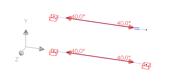
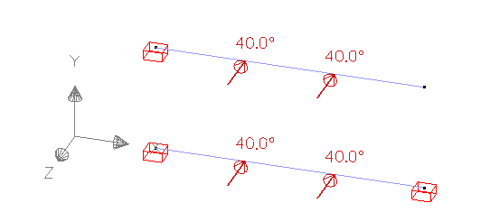
| Load 2: Lineair gradient in local y’ direction |
||
| Load 3: Lineair gradient in local z’ direction |
||
| Mesh | No. of divisions | 8 |
Results
Load 1: global temperature change
Handcalculation
- Case 1: cantilever beam
Since the beam can lengthen/ shorten, the temperature load will extend the beam
![\[ \delta_x=\alpha \cdot \Delta T\cdot L=0.000 012 / ^{\circ}C\cdot 40^{\circ}C\cdot 5m=2.4mm\]](https://support.buildsoft.eu/wp-content/ql-cache/quicklatex.com-e33c783be7273d07206b208a716adb20_l3.png "Rendered by QuickLaTeX.com")
- Case 2: fixed beam
Since the beam cannot lengthen/ shorten, the temperature load will result in axial force.
The increase in temperature will want to lengthen the beam. To counteract this deformation, a compressive force must be created. So the normal force in Diamonds will have a negative sign.
![\[N=\alpha \cdot \Delta T\cdot A\cdot E=0.000 012 / ^{\circ}C\cdot 40^{\circ}C\cdot 11553mm^2\cdot 210000N/mm^2=1164.46kN\]](https://support.buildsoft.eu/wp-content/ql-cache/quicklatex.com-5b70e4a0ed9f19d6c380d8fba81612e7_l3.png "Rendered by QuickLaTeX.com")
| Independent reference | Diamonds | Difference | ||
|---|---|---|---|---|
| Case 1 | Horizontal deformation  |
2.4mm | 2.4mm | 0,00% |
| Case 2 | Axial force  |
-1164.46kN | -1164.46kN | 0,00% |
Load 2: lineair gradient in local y’ direction
Handcalculation

- Case 1: cantilever beam
Since the beam can lengthen/ shorten, the gradient will cause an elongation of the upper fiber and a shortening of the non-fiber. The combination of both results in a downward deformation.![\[ \varphi_z=\frac{\alpha \cdot \Delta T\cdot L}{h}=\frac{0.000 012 / ^{\circ}C\cdot 40^{\circ}C\cdot 11553mm^2\cdot 5m}{500mm}=0.2750^{\circ}\]](https://support.buildsoft.eu/wp-content/ql-cache/quicklatex.com-5ba07cd7852c363498fb2e0e5cd9f3ae_l3.png "Rendered by QuickLaTeX.com")
![\[ \delta _y=\frac{\alpha \cdot \Delta T\cdot L^2}{2 \cdot h}=\frac{0.000 012 / ^{\circ}C\cdot 40^{\circ}C\cdot (5m)^2}{2 \cdot 500mm}=12.0000mm\]](https://support.buildsoft.eu/wp-content/ql-cache/quicklatex.com-f2765bd51248a3a5e8e054e4a87a5d34_l3.png "Rendered by QuickLaTeX.com")
- Case 2: Fixed beam
Since the beam cannot lengthen/ shorten, the gradient will cause an elongation of the upper fiber and a shortening of the non-fiber. To counteract this deformation, a compressive force must be created in the upper fiber and a tensile force in the lower. So the bending moment in Diamonds will be drawn on the lower side of the beam.![\[M_{y'}=\frac{\alpha \cdot \Delta T\cdot E\cdot I_y}{h}=\frac{0.000 012 / ^{\circ}C\cdot 40^{\circ}C \cdot 4.82\cdot 10^8 mm^4}{500mm}=97.17kNm\]](https://support.buildsoft.eu/wp-content/ql-cache/quicklatex.com-0b3b0ce714d28764af2db4b7c4b67bf6_l3.png "Rendered by QuickLaTeX.com")
| Independent reference | Diamonds | Difference | ||
|---|---|---|---|---|
| Case 1 | Angular rotation  |
0.2750° | 0.2750° | 0,00% |
Horizontal deformation  |
12.0000mm | 12.0000mm | 0,00% | |
| Case 2 | Bending moment  |
97,17kNm | 97,17kNm | 0,00% |
Load 3: lineair gradient in local z’ direction
Handcalculation
- Case 1: cantilever beam
Since the beam can lengthen/ shorten, the gradient will cause an elongation of the upper fiber and a shortening of the non-fiber. The combination of both results in a downward deformation.![\[ \varphi_z=\frac{\alpha \cdot \Delta T\cdot L}{b}=\frac{0.000 012 / ^{\circ}C\cdot 40^{\circ}C\cdot 11553mm^2\cdot 5m}{200mm}=0.6875^{\circ}\]](https://support.buildsoft.eu/wp-content/ql-cache/quicklatex.com-5674059d9decc19b05761304f610e30e_l3.png "Rendered by QuickLaTeX.com")
![\[ \delta _y=\frac{\alpha \cdot \Delta T\cdot L^2}{2 \cdot b}=\frac{0.000 012 / ^{\circ}C\cdot 40^{\circ}C\cdot (5m)^2}{2 \cdot 200mm}=30.0000mm\]](https://support.buildsoft.eu/wp-content/ql-cache/quicklatex.com-291c9e081314084fd9cb25d1321acc12_l3.png "Rendered by QuickLaTeX.com")
- Case 2: Fixed beam
Since the beam cannot lengthen/ shorten, the gradient will cause an elongation of the upper fiber and a shortening of the non-fiber. To counteract this deformation, a compressive force must be created in the upper fiber and a tensile force in the lower. So the bending moment in Diamonds will be drawn on the lower side of the beam.![\[M_{y'}=\frac{\alpha \cdot \Delta T\cdot E\cdot I_y}{b}=\frac{0.000 012 / ^{\circ}C\cdot 40^{\circ}C \cdot 2.14\cdot 10^7 mm^4}{200mm}=10.79kNm\]](https://support.buildsoft.eu/wp-content/ql-cache/quicklatex.com-1d7a91045857eed09c3e66c125559983_l3.png "Rendered by QuickLaTeX.com")
| Independent reference | Diamonds | Difference | ||
|---|---|---|---|---|
| Case 1 | Angular rotation  |
0.6875° | 0.6875° | 0,00% |
Horizontal deformation  |
30.0000mm | 30.0000mm | 0,00% | |
| Case 2 | Bending moment  |
10.79kNm | 10.79kNm | 0,00% |
References
- Hibbeler, R. (2006). Sterkteleer, 2/e. Pearson Education.
- Weaver, W., & Gere, J. M. (1990). Matrix analysis of framed structures Table B-2. In Springer eBooks. https://doi.org/10.1007/978-1-4684-7487-9
- Tested in Diamonds 2023r01.
