Diamonds can verify the shear force in a discrete point of a plate (= punching shear reinforcement) but it will not verify the shear force in the entire plate (is VEd < VRd.c?). Why?
- Well, the shear force is the second derivative of the deformations and is therefore less accurate than any other result you can retrieve in Diamonds.
- And second, the shear force is very sensitive to peaks.
So even if Diamonds would verify the shear in the entire plate, you would still have to interpret the results when a plate is not sufficient.
This article explains how to manually verify the shear force in a plate using Excel. We use a one-way slab in the workflow , so it is obvious to you which shear force to combine with which reinforcement result. Once you get the hang of it, you can extend the Excel to a two-way slab.
Workflow
- Download the zip-file at the bottom of this article.
- Unzip it (click with right mouse button on zip-file and choose “Extract to…”).
You’ll find a Diamonds model (*.bsf-file) and an Excel-file. - Open the Diamonds model (*.bsf-file).
- Make sure your units are defined as in the printscreen below:

- Run the elastic analysis
 and concrete design
  .
. - Show the results for the shear force Vx in surfaces in a ULS FC enveloppe.
- Select the plate and click on
 .
.
This opens the results table.
It’s important that you select the desired plate before clicking on. Even if your model only contains one plate! The data we’ll be requesting in the next step can only be shown for one plate at a time.
- In the results table, click on
 .
. - Make sure Label, the results in All meshnodes and the Mesh coordinates are checked.
It’s important that you check the same options, otherwise the table count in your Excel-file won’t correspond to the table count used in this example.
- Click on
 .
.
This copies the content of the table to the clipboard. - Open the Excel-file.
- Go to the first tab page 1. Internal forces.
- Select cell A1 and hit CTRL + P.
This pastes the table from the clipboard to Excel.
If the shear force is 1000 times too big, like in the image below, your computer probably uses a ” . ” as decimal separator instead of ” , “. Follow the instructions in this article to fix it.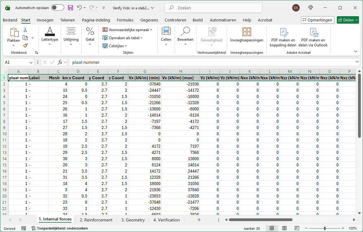
- Go to Diamonds.
- Show the reinforcement results in the plate.
- Select the plate and click on .
This opens the results table. - Click on .
This copies the content of the table to the clipboard. - Go to Excel.
- Select tab page 2. Reinforcement.
- Select cell A1 and hit CTRL + P.
This pastes the table from the clipboard to Excel.
- Select tab page 3. Geometry.
Enter the information in from the blue cells.
The orange cells are National Determined Parameters (NDP). We’ve taken the values from Eurocode without a national annex. You can change them if needed.
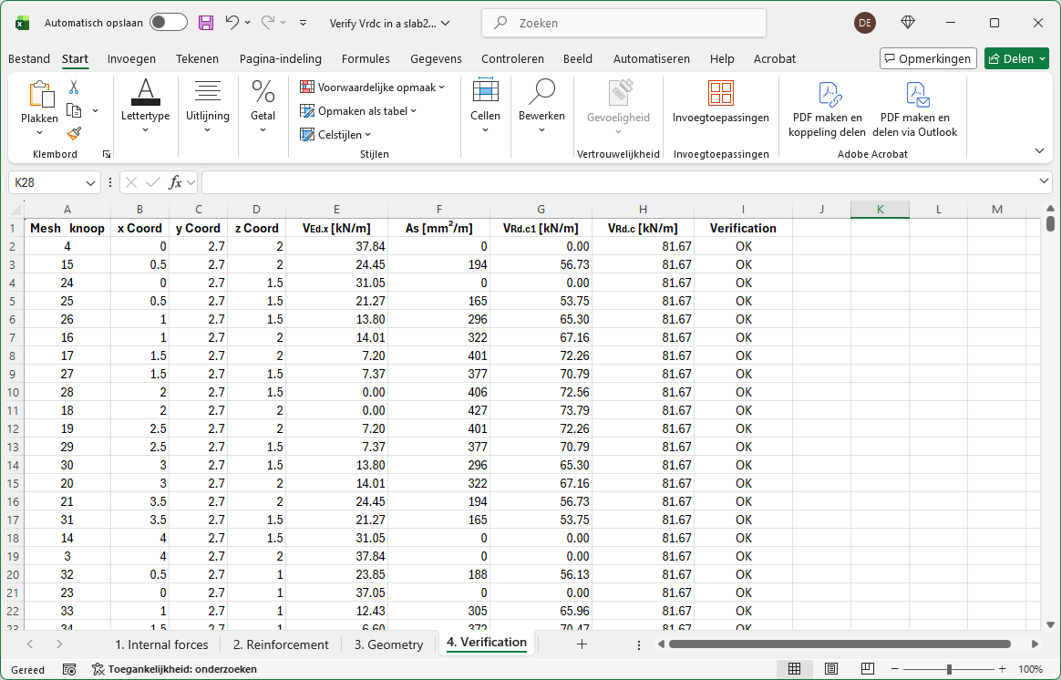
- Select tab page 4. Verification.
- Columns A until D are a copy of tab page 1. Internal forces.
- Columns E until I contain formula. The model in the attachment contained 45 mesh nodes. Extend the formula if your model contains more mesh nodes.
- Columns G and H of tab page 1. Internal forces contain the minimum and maximum shear force in each mesh node.
Column E of tab page 4. Verification, will take the maximum of their absolute values. - Column F takes the maximum of the calculated tensile reinforcement (given in 2. Reinforcement) and the defined practical reinforcement (given in 3. Geometry).
EN 1992-1-1 (6.2a) clearly states the tensile reinforcement should be used to calculate VRd.c1, so the minimum reinforcement is ignored.
In the demo model, the tensile stresses are located at the bottom of the slab. This is not always the case in a realistic model: both positive and negative moments may occur in the same plate. You will need to update the formulas in Excel so that, for each mesh node, the formula checks whether the tensile stresses are at the top or bottom and then includes the corresponding tensile reinforcement in the formula. - Column G calculates VRd.c1 according to EN 1992-1-1 (6.2a).
The implemented formula in the Excel assumes there is no normal force in the slab present. - Column H takes the maximum of VRd.c1 (given in column G) and VRd.c2 (given in 3. Geometry).
- Column I compares VEd.x to VRd.c. If VEd.x is > VRd.c, you’ll see “NOT SUFFICIENT”, else you’ll see “OK”.
If the shear force at a certain mesh node is not sufficient, you’ll need to check if the issue is related to peaks and might be ignored. If it cannot be ignored, you’ll either need to increase VRd.c (by adding more practical reinforcement) or apply shear reinforcement.