This article explains how to send one or more Tekla Structural Designer nodes to PowerConnect, using BIM Expert.
1. Preparation in Tekla Structural Designer
The conversion is based on the .cxl file format. The .cxl file format is an XML based neutral file format that allows applications to link with Tekla Structural Designer. Tekla Structural Designer accepts and produces files in the .cxl neutral file format.
2. Send model from Tekla Structural Designer to PowerConnect
2.1 From Tekla Structural Designer to BIM Expert
In the Model tab, select ‘Import’. Next, choose ‘CXL’. Click ![]() to continue.
to continue.
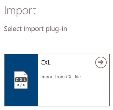
The model is now in BIM Expert.
2.1.1 Material & section mapping
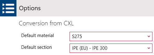
Most common materials and sections are mapped according to the TSD neutral file mapping conventions. If there is no match found, a default section and material will be applied. You can specify these defaults in ‘File > Settings > CXL’
2.2 From BIM Expert to PowerConnect
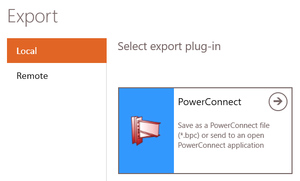
In the Model tab, select ‘Export’. Next, choose the destination software, namely PowerConnect. Click ![]() to continue.
to continue.
2.2.1 Settings
You can choose to either
- save the model as *.bpc-file
- send the model to the current open PowerConnect instance – you see all open instances of PowerConnect
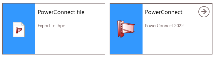
Select your choice and click ![]() to continue.
to continue.
2.2.2 Automatic detection of connection components
BIM Expert automatically detects existing connection components in the model. You get an overview of all found connection components and whether they can be transferred to PowerConnect.
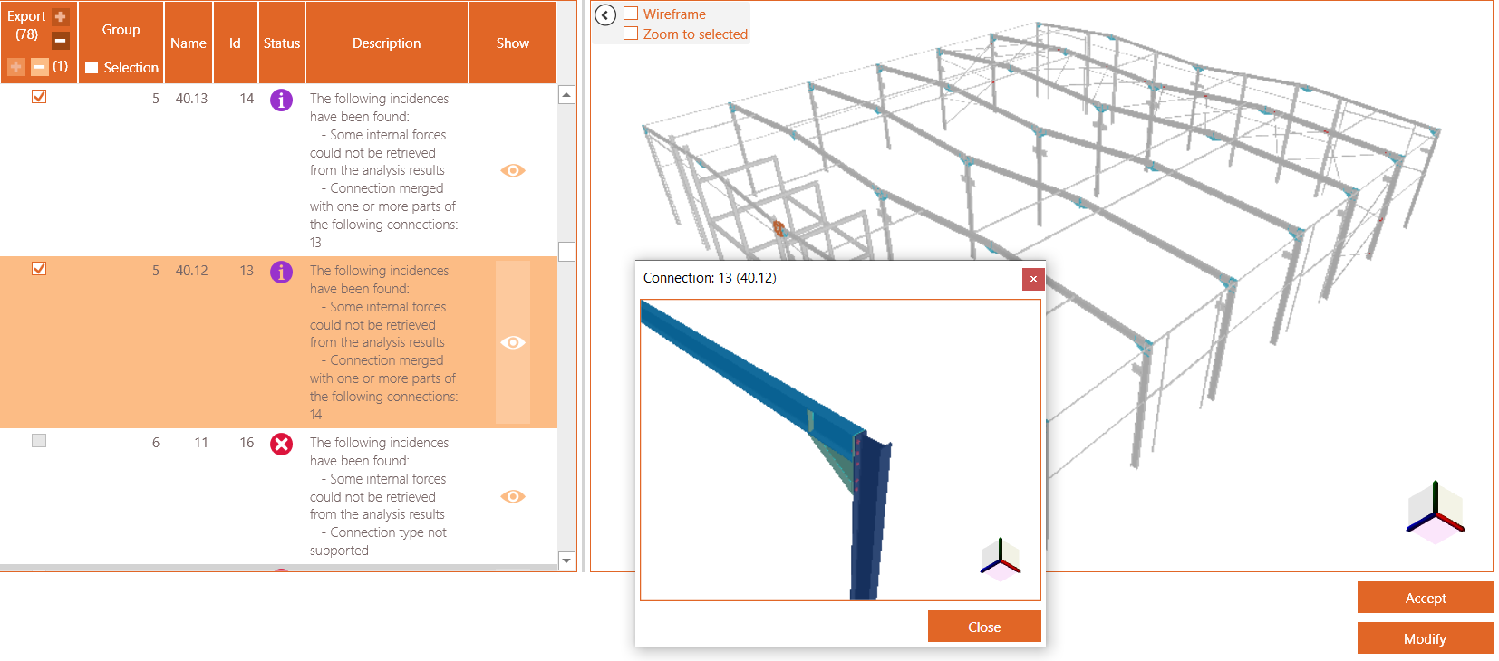
Use the eye button in the ‘Show’ column to see a detailed popup window of the connection.
Possible descriptions are
- Some internal forces could not be retrieved from the analysis results
No (or not all) internal forces are present from the source software. - The connection is identical to connection(s) {IDs} and therefore has been grouped
Identical connections will be treated as one connection. You must only calculate the connections one, with envelope forces. - Connection merged with one or more parts of the following connection: {ID}
The connection is merged with other one to create a more complex connection (e.g. two shear connections to beam-column are merged to design a double-sided shear connection) - Connection divided into <….> connections
A complex connection has been split up into smaller PowerConnect connections - The connection bars/plates with following ID’s could not be recognized: {IDs}
The connection is recognized and can be calculated with PowerConnect, execpt for these bars/plates, with given Ids - Connection type not support
This connection configuration cannot be calculated by PowerConnect, so it will not be transferred.
If no connections are found, you will see

2.2.3 Add connections manually via Connection Assembler
You can make your own connections by clicking ‘Modify’ (see image above).
In the next window, you see on the left hand side the BIM Expert model. In this window you see the regular scroll, 3D orbit and pan functions. On the right hand side, there is on top an overview of created connections and at the bottom, the ‘Create’ button to make new connections.

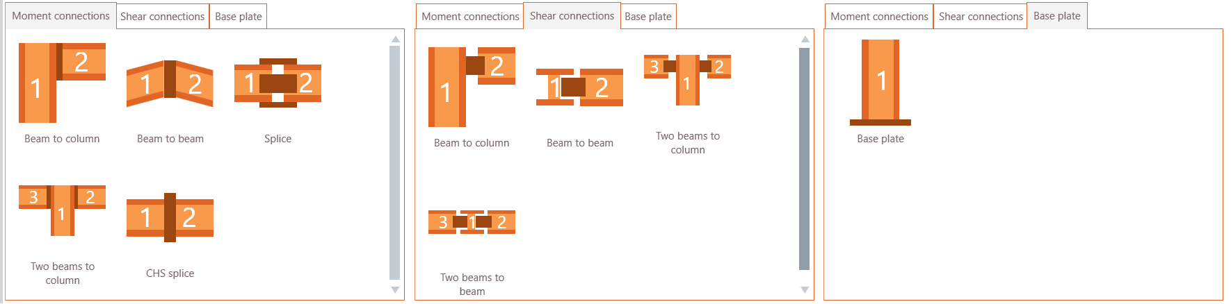
In the next step you choose the connection type
- Moment connections: beam-column, beam-beam, splice, beam-column-beam or CHS splice
- Shear connections: beam-column or beam-beam, beam-column-beam or beam-beam-beam
- Base plate connections
After selecting for example ‘Beam to column’ you select the column and next the beam element from the 3D image on the left hand side. Click once on the column element and next on the beam element. BIM Expert will list and indicate which connections are possible:
- Beam to column flange > possible, and marked with

- Beam to column web > not possible, and not marked – you can click the orange arrow
 at the end to fold out the details and see why this connection is not possible.

On clicking ‘Create’, the connection is added to the list of connections on top. Having selected the beam-column type, you can now continue making this type of connections, until you click ‘Change pattern’.
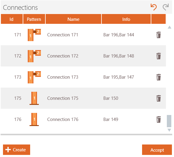
When the connection definition is finished, you click ‘Close’ and ‘Accept’ to continue to PowerConnect.
If you have chosen to open the model directly in PowerConnect, you will get a notification in PowerConnect on the right side. You can now choose to load the model or to delete it (by using the ‘x’).

3. Final steps in PowerConnect
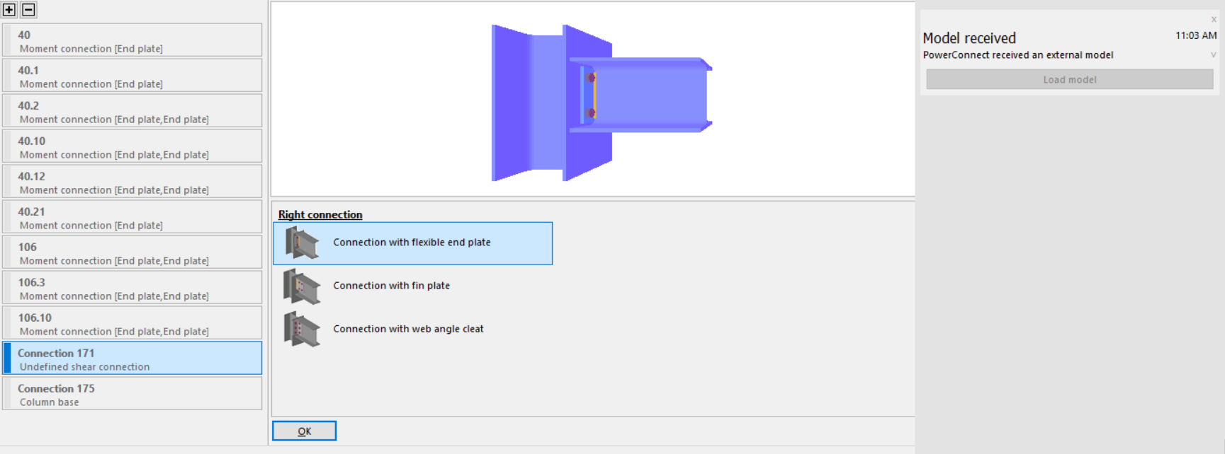
All connections will appear in the node list on the left side (as from PowerConnect 2021). Remember that all identical connections will be grouped as 1.
Connections made with the Connection Assembler might appear with a red bar and as ‘Undefined’. The connector type must be chosen (e.g. end plate, shear plate, welded, angles etc)
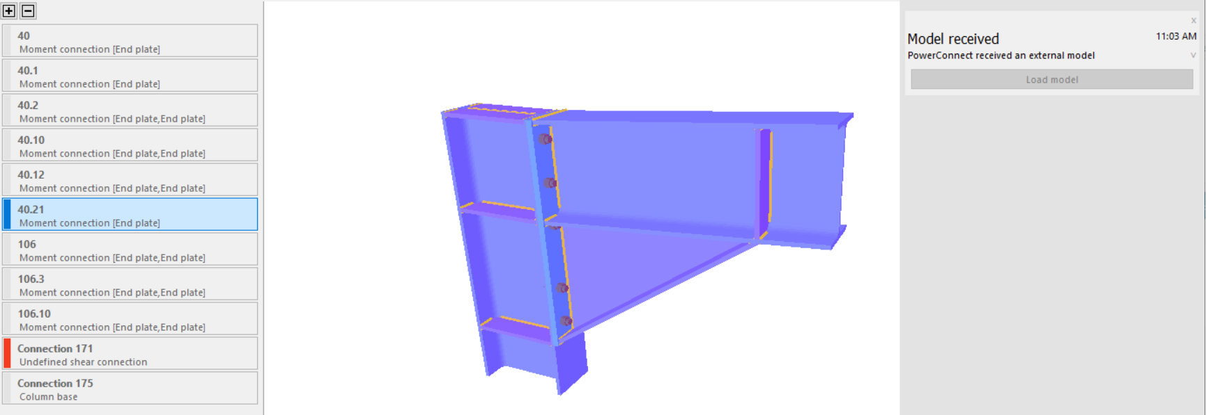
Click on this connection to set the connector.
If no loads or internal forces were transferred, you should add loads in PowerConnect, in order to have a proper design of the connections.
