
Reason
Diamonds shows the real behaviour of the structure, while hand calculations/ daily reasoning make assumptions that are only valid for some cases. For example:
- The hand calculations of a plate are only valid for a plate strip in the middle of the plate, far enough from the edges.
- Préslabs is plate type which behaviour is rahter a two-way slab than a one-way slab. Yet in handcalculations, a préslab is mostly approached using one-way slab behaviour.
If the assumptions used during hand calculations are modelled in Diamonds, Diamonds will give similar results as the hand calculations.
The question is if these hand-calculations-assumtions comply to the real behaviour of the structure? If the boundary conditions and plate-behaviour are representative for the real behavior of the structure, the Diamonds results are the most correct.
Example
Consider the example building from the image below (model attached at the end of this article). The walls have been set invisible. The loading is 12kN/m² on both the roof and the floor. Using hand calculations a bending moment of 167kNm is expected in the beam. Yet in Diamonds only a maximum bending moment of 4,0kNm is found.
\[{q=12kN/m^2 \cdot 0.5 \cdot 5.5m \cdot 2 = 66kN/m}\]
\[M_y=\frac{66kN/m \cdot (4.5m)^2}{8} = 167kNm\]
| Geometry (the walls have been set invisible) | Diamonds result for My |
|---|---|
 |
 |
The following changes have been made to make the Diamonds-results correspond to hand calculations:
- Select all walls. Remove the no tension at the top of a wall-condition. ‘No tension at the top of a wall’ is something you cannot simulate in simple hand calculations.
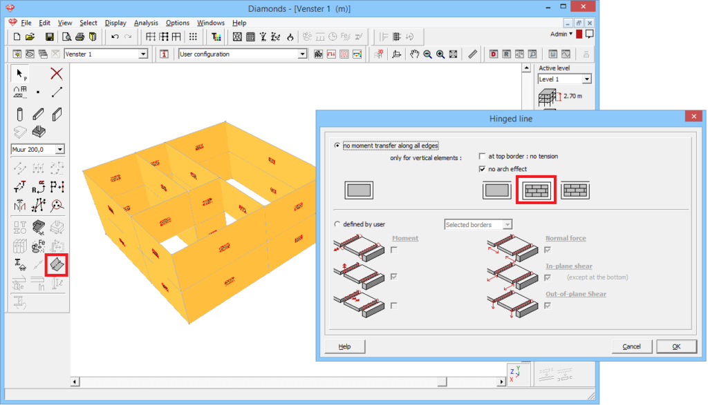
- Define the slabs as bearing in one direction instead of préslabs. In the hand calculation, it is assumed that 50% of the loading goes to the beam. This is only true, if the slabs are bearing in one direction.

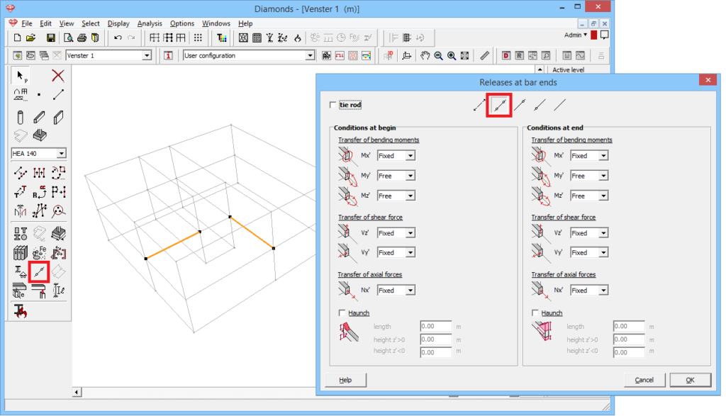
- Put hinges at the bar ends.
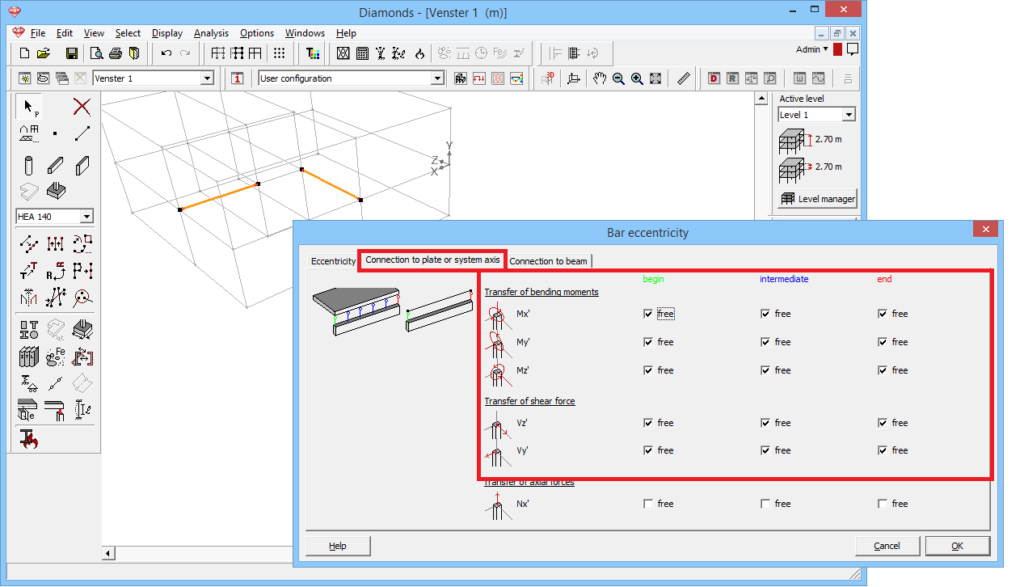
- Place the beams eccentric. Allow only the transfer of normal force in the rigid links.

- Define hinges on the floor edges.
- Turn off the transfer of moment, normal force and in-plane shear force for all edges.

- Additionally, turn off the transfer of out-of-plane shear for all edges parallel to the bearing direction.

- Turn off the transfer of moment, normal force and in-plane shear force for all edges.
- The Diamonds model now approximate the hand calculations well: