
Introduction
Diamonds allows the modelling of masonry. Besides adding a new material to the library, you also need to define the behaviour correctly.
The purpose of this article is to give you more insight in the Diamonds options regarding the behaviour of masonry walls. We will also tackle some pitfalls related to that behaviour.
Notes:
- Our support-website explains how you can add a new masonry quality to the material library. You can find some mechanical properties for masonry in BuildSoft tutorials, but don’t copy-paste them blindly into Diamonds!
Masonry is a combination of bricks and mortar. The bricks come in different qualities and sizes. So does the mortar. Thus, there is no such thing as ‘THE’ masonry quality, only ‘A’ masonry quality. Make sure the mechanical properties you enter in Diamonds, correspond to the bricks + mortar you’re planning to use. Directions on how to calculate the mechanical properties for masonry, can be found in Eurocode 6. - Although Diamonds allows the modelling of masonry (behaviour), Diamonds DOES NOTsupport the DESIGN of masonry according to Eurocode 6. So yes, Diamonds can calculateinternal forces in masonry walls. But no, Diamonds cannot tell if those masonry walls can bear those internal forces.
Options for behaviour
Once a masonry quality has been assigned to a wall, you can specify the behaviour of that wall using the button  . The lay-out of this dialog is as follows:
- In the lower part, you can define each degree of freedom separately as free/valued/fixed. By default, all degrees of freedom are fixed, meaning all internal forces can be transferred though the borders.
- The upper part contains predefined settings for masonry walls. Once you selected a certain option here, you’ll notice that the content of the lower part changes depending on the option(s) you selected.
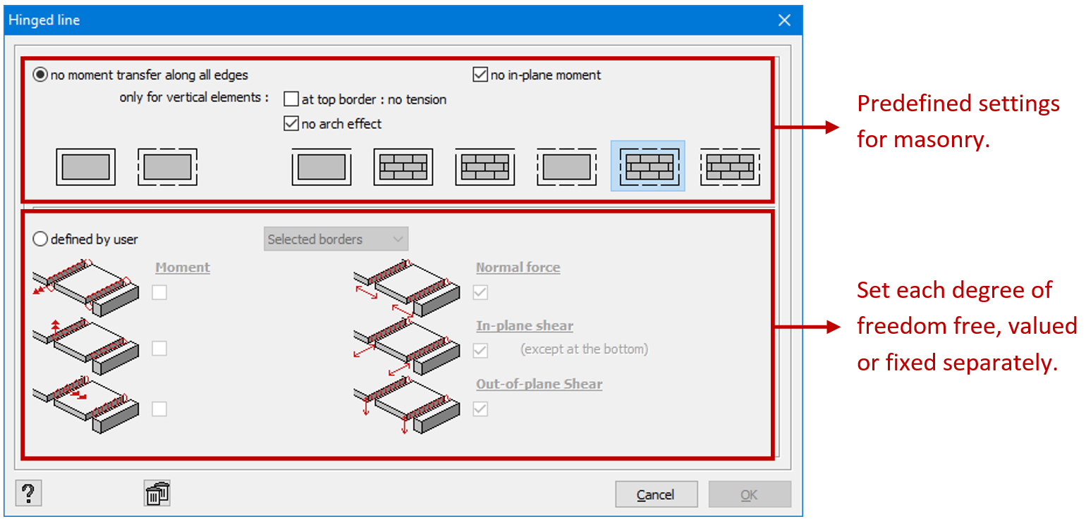
In the next paragraphs, we investigate the predefined settings for masonry walls, thus focussing on the upper part of the dialog:
Influence ‘At top border no tension’
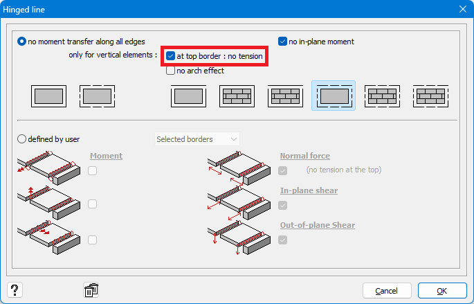
This option is used to prevent plates from pulling on the walls when loaded. Checking this option, results in an iterative calculation.
 |  | |
| Deflection δy | 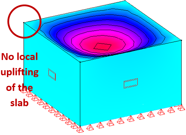 | 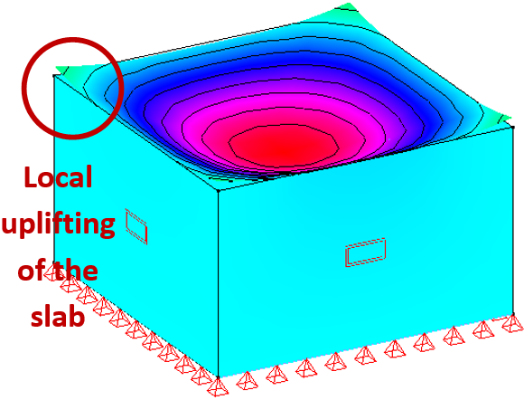 |
| Axial force Nzz | 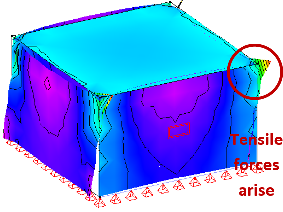 | 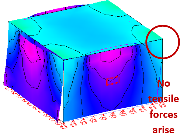 |
Notes:
- By checking the option ‘At top border: no tension’, the elastic analysis will become an iterative calculation. Consequences:
- Increasing calculation time (if you don’t have other non-linear behaviour).
- An iterative calculation doesn’t always convert to a solution. Meaning, it’s not guaranteed that Diamonds will always find a way to transfer the loads to the foundation while meeting all the boundary conditions you imposed. In case no convergence is found, Diamonds will show a warning.
Because this option makes the calculations more complex, it’s advised to use this option in a more final stage of the design.
- By checking the option ‘At top border: no tension’, you prevent tension from occurring at the top border of the walls. However, this option cannot eliminate tension in the ‘field’ of the wall.
Influence ‘No arch effect’
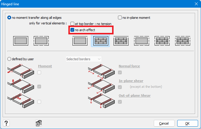
This option will describe how the loads are transferred downward.
Conclusion: when the option  is checked, the wall transfers its loads directly to the beam as if the beam was directly loaded with q without the wall being present.
Notes:
- In reinforced concrete the arch effect can originate. For masonry, it is up for discussion. So for safety’s sake, it is commonly assumed that the arch effect cannot originate the masonry.
- The option will disable all components for membrane action in the stiffness matrix, except for the component that determines Nxx. If you would use a plate bearing in one direction (
 >
>  ), that would give the same result as .
The option and a membrane ( >  ) will not give the same results as a membrane will have all components for membrane enabled.
Influence ‘No in-plane transfer’
We want to test the influence of the option ‘no in-plane moment’. In the previous paragraph we learned that for the sake of safety, the option ‘no arch effect’ must be checked for masonry. So we did.
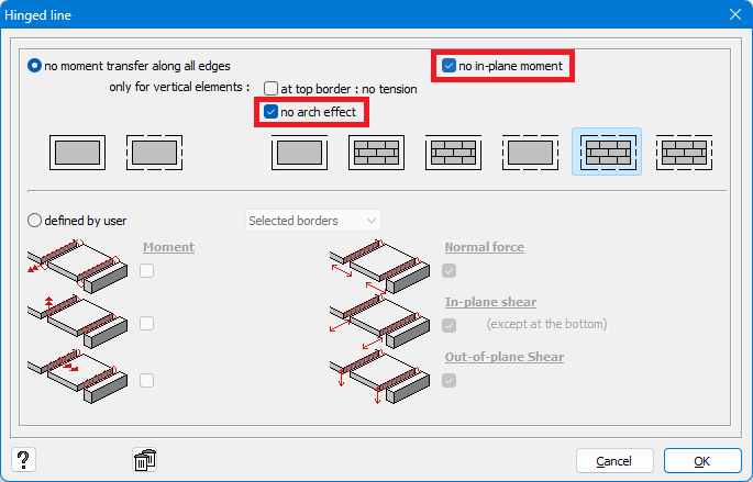
In a wall without openings
To test the effect of the option ‘No in-plane moment’, we use the model below.
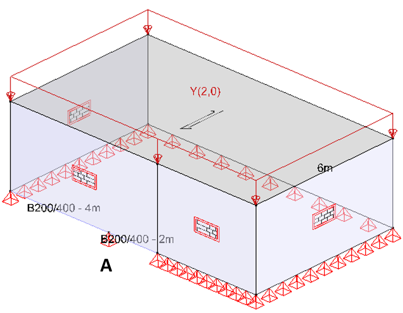
If the wall bears the loads perfectly downward, the bending moment in point A of the beam B200/400 must be:
![\[M_{y.A}=\frac{q \cdot \left( a^3 + b^3 \right)}{8 \cdot \left( a^3 + b^3 \right)}=\frac{6 \text{kN/m} \cdot \left( 4^3 + 2^3 \right)}{8 \cdot \left( 4^3 + 2^3 \right)}=9.0 \text{kNm}\]](https://support.buildsoft.eu/wp-content/ql-cache/quicklatex.com-ac3e007116acb2aa64fdea662e034dfd_l3.png "Rendered by QuickLaTeX.com")
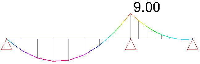
Let’s find out if we can approximate that 9kNm (mesh size: max = 0,8m; min = 0,4m).
 |  | |
| Geometry | | 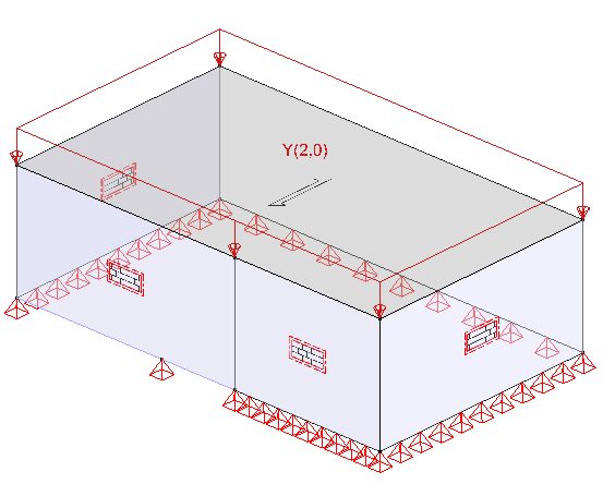 |
| Bending moment in beam | 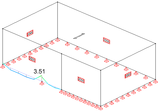 | 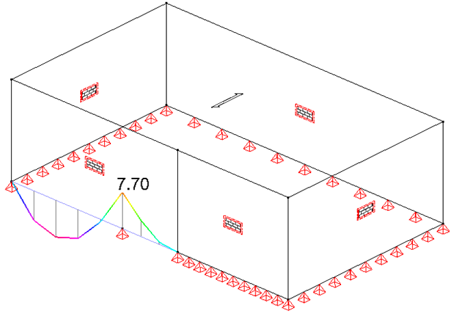 |
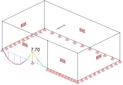
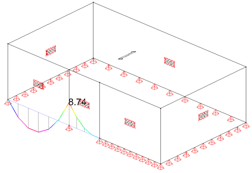
The shape of the bending moment is more in line with the expectations when the option is checked. But the bending moment is not (yet) of the same magnitude as the isolated beam. This is caused by the position of the mesh nodes. The mesh nodes in the wall must be aligned with the ends of the beam, to obtain that perfect behaviour. The only way to force this, is by dividing the wall above the beam ends (we continue with the model in which the option is checked).
| Not divided | Divided | |
| Geometry | 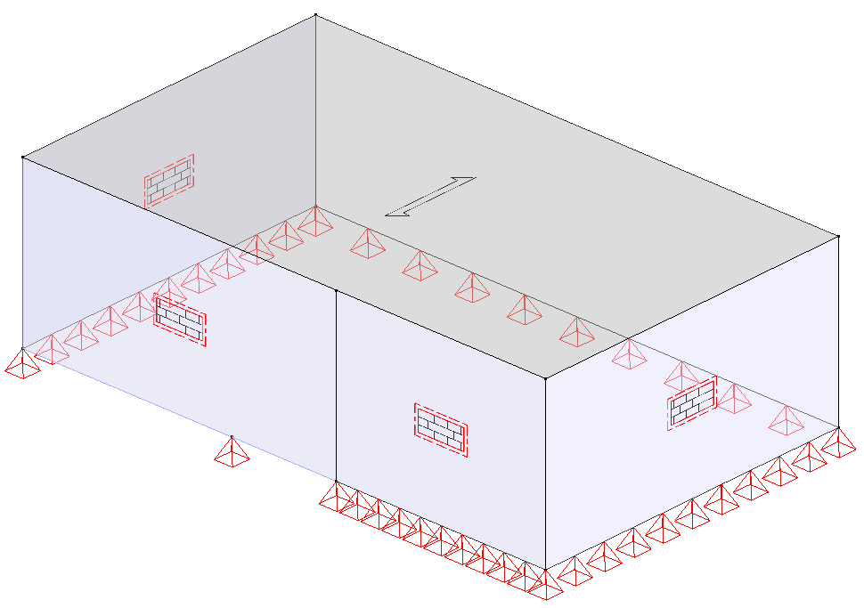 | 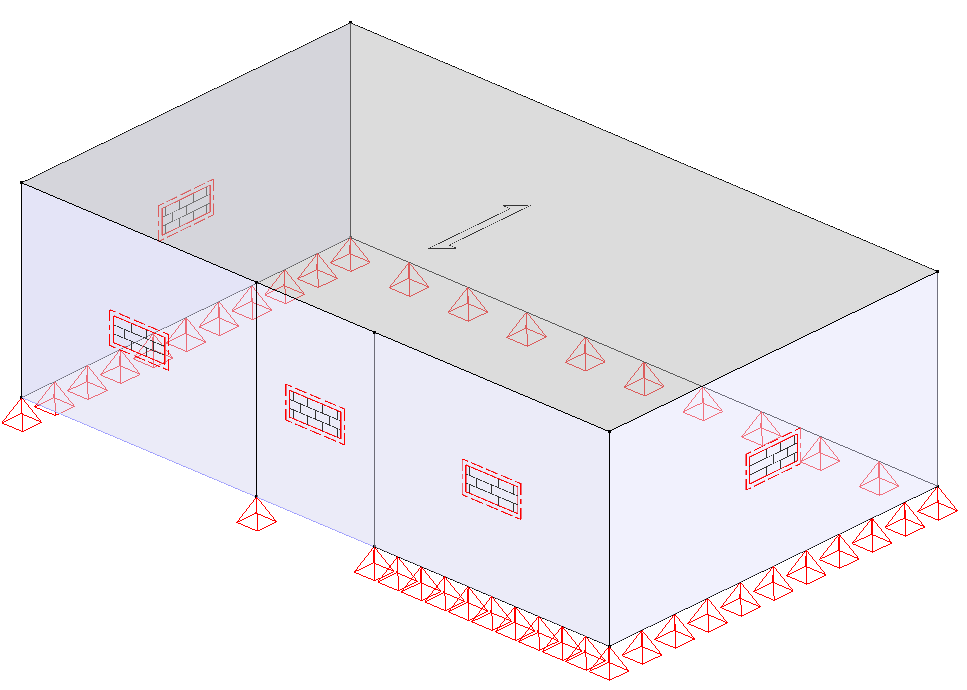 |
| Mesh (walls along the side and back were set invisible to increase readability) | 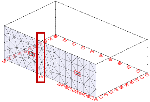 | 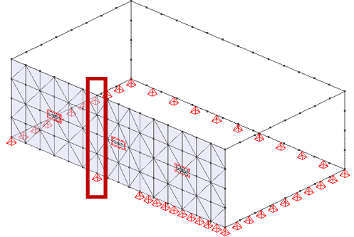 |
| Bending moment My |
|
|
The division does improve the results significantly (reducing the deviation from 15% to 3%).
In a wall with openings
To test the effect of the option ‘No in-plane moment’, we use the model below.
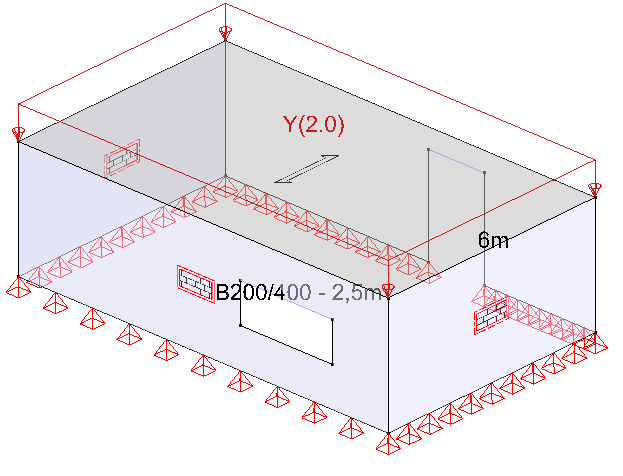
If the walls bear the loads perfectly downward, the bending moment in the beam B200/400 above the window must be 4,69kNm and have a parabolic shape :
![\[M_y=\frac{q \cdot l}{8}=\frac{6 \text{kN/m} \cdot \left( 2.5m \right)^2}{8}=4.69 \text{kNm}\]](https://support.buildsoft.eu/wp-content/ql-cache/quicklatex.com-26a9b2eefecfb2562ee6352726525d31_l3.png "Rendered by QuickLaTeX.com")
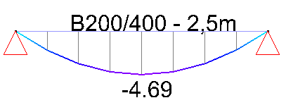
Let’s find out if we can approximate that 4.69kNm (mesh size: max = 0,8m; min = 0,4m). In this paragraph we learned that the option ‘no in-plane moment’ must be checked for masonry and that the mesh nodes above the beam ends must be aligned. So we did. Result:
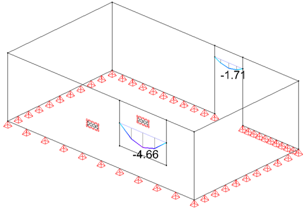
This is a good approximation (less than 1% deviation).
Note: Without the division, the bending moment in the beam has the shape of a build-in beam (restrained at the ends). You might think that applying hinges to the beam, will resolve the issue, but it doesn’t affect the results.
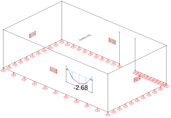 No division, no hinges | 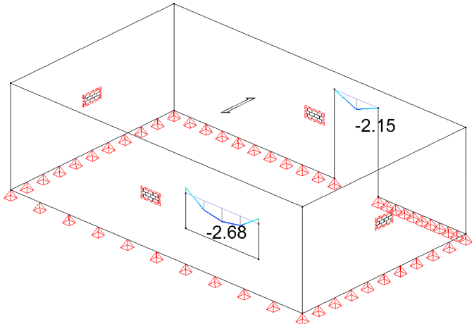 No division, hinges applied |
Conclusion: workflow for defining masonry in Diamonds
- Calculate the mechanical properties of masonry using Eurocode 6. Create a new material in Diamonds using these mechanical properties. Assign this material to the masonry walls.
- For perfect vertical-load-bearing behaviour:
- Check the option ‘no arch effect’ and the option ‘no in-plane moment’.
Pay attention to the horizontal stability of the building. - Divide the wall above the ends of a beam so the mesh triangles are aligned.
- Check the option ‘no arch effect’ and the option ‘no in-plane moment’.
- Turn the option only off for walls in which tension arises at the top.
- With the options and checked, the relevant walls lose their stabilizing function. A structure containing only walls with these options checked, will be sensitive for horizontal displacements (due to for example wind loads).
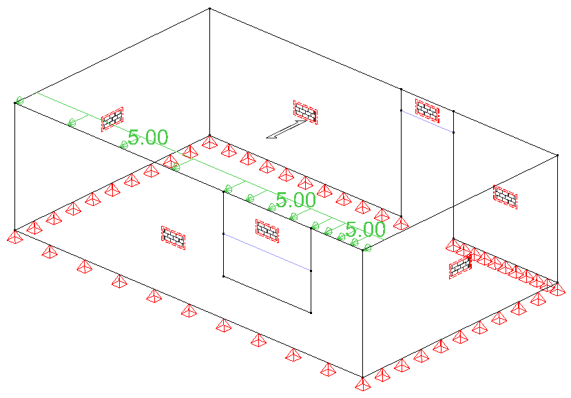 Horizontal wind load | 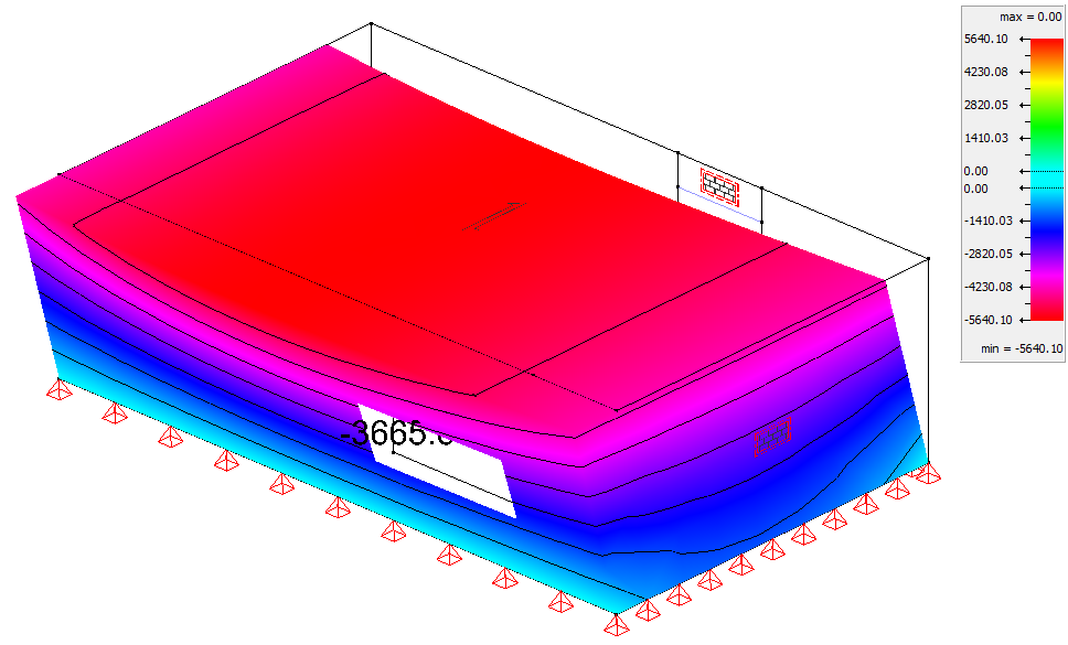 Horizontal displacement [mm] |