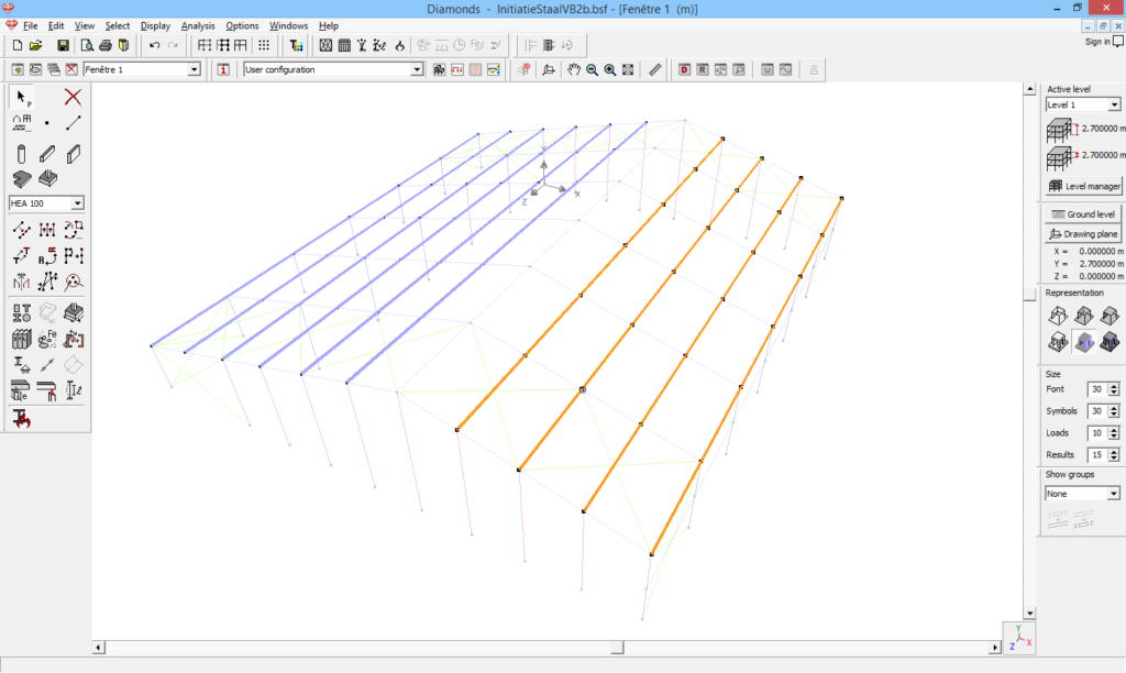
- Select the line(s).

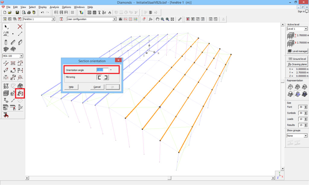
- Click on
 .
. - Enter the desired angle and hit ‘OK’.

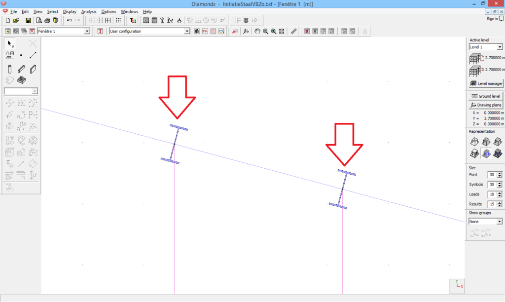
- Verify the orientation of the sections in a 2D view. In the image below, a front view is used.

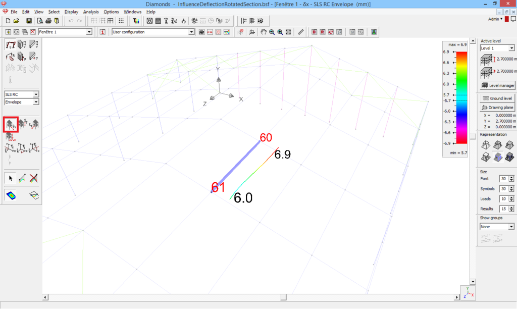
Note: don’t get confused in the results! For example a beam is rotated for 15° (download the model at the end of this article).
- In point 60, the horizontal deformation equals 6.9mm and the vertical deformation is 52mm. These results are according to the GLOBAL XYZ coordinate system.


- When you select a bar and open the detailed results
 , the results are shown according to the LOCAL x’, y’, z’ coordinate system. Since the beam is rotated, the LOCAL and GLOBAL coordinate system will no longer have the same orientation and you will not retrieve the 6.9mm and 52mm. The deformations according to the LOCAL coordinate system are the vectorial sum of the global deformations.
 =
= 
 cos (15°) +
 cos (75°) = 6.9 mm
  cos (15°) + 52mm
  cos (75°) = 20.1mm
 =
= 
 sin (15°) +
 sin (75°) = 6.9 mm
  sin (15°) + 52mm
  sin (75°) = 48.5mm

