This article explains how to send a Tekla Structures model to PowerConnect, using BIM Expert.
There are 2 ways to send your connections from Tekla Structures to PowerConnect:
- Connections components only (easiest, see video above):
- connection components must be present in the model – only they will be transferred
- requires no analytical model creation
- additional connections via Connection Assembler are not possible
- Analysis model:
- connection components can be present in the model and will be recognized
- requires the creation of an analytical model
- extra connection can be added via the Connection Assembler
1. Preparation in Tekla Structures
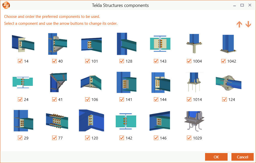
The transfer is based on the connection components. Make sure you have some in your model. The components below are supported by PowerConnect.
2. Send model from Tekla Structures to PowerConnect
2.1 From Tekla Structures to BIM Expert
There is more than 1 way to send connections from Tekla Structures to BIM Expert. You can either start from
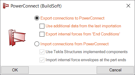
- Additional data: data that came from a previous transfer, but is not supported by Tekla Structures. This information is kept and can now be taken along in the current transfer (e.g. seismic information, soil layers, …)
- Internal forces from ‘End Conditions’. The End Conditions tab can be found in the element’s UDA (User Defined Attributes)
2.1.1 Selection of elements
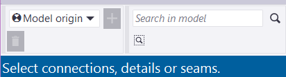
Select the elements and confirm your selection by clicking the middle mouse button (mouse wheel). You will get an overview of all selected connection components: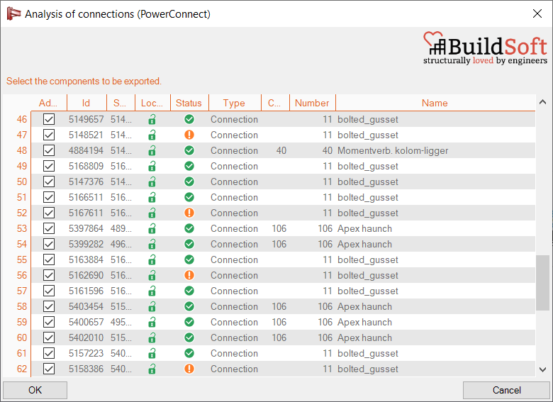
2.1.2 Component bundles
If you have turned off the option to reduce the dialog windows, you will get an overview of all connections components in the model and the possibility to bundle components.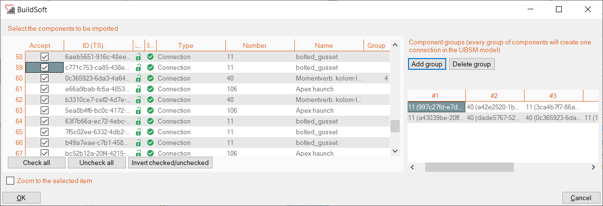 In this window you can do 2 things:
- Select the connections to be included in transfer, via the checkbox in the ‘Accept’ column
- Bundle connection components into larger complex connection groups:
- Position this window in a corner of your screen, because once you start adding groups, the window position is locked.
- Click ‘Add group’ to select the components.
- Select the components by clicking the component arrow. All components should logically be around a single node of course.
- Confirm the selection with the middle mouse button.
- The group is now listed with the reference ids of the individual components.
2.2 From BIM Expert to PowerConnect
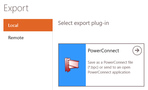
In the Model tab, select ‘Export’. Next, choose the destination software, namely PowerConnect. Click ![]() to continue.
to continue.
2.2.1 Settings
You can choose to either
- save the model as *.bpc-file
- send the model to the current open PowerConnect instance – you see all open instances of PowerConnect
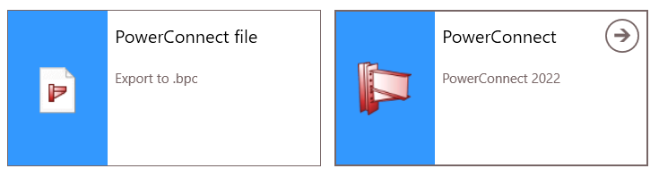
Select your choice and click ![]() to continue.
to continue.
2.2.2 Automatic detection of connection components
BIM Expert automatically detects existing connection components in the model. You get an overview of all found connection components and whether they can be transferred to PowerConnect.
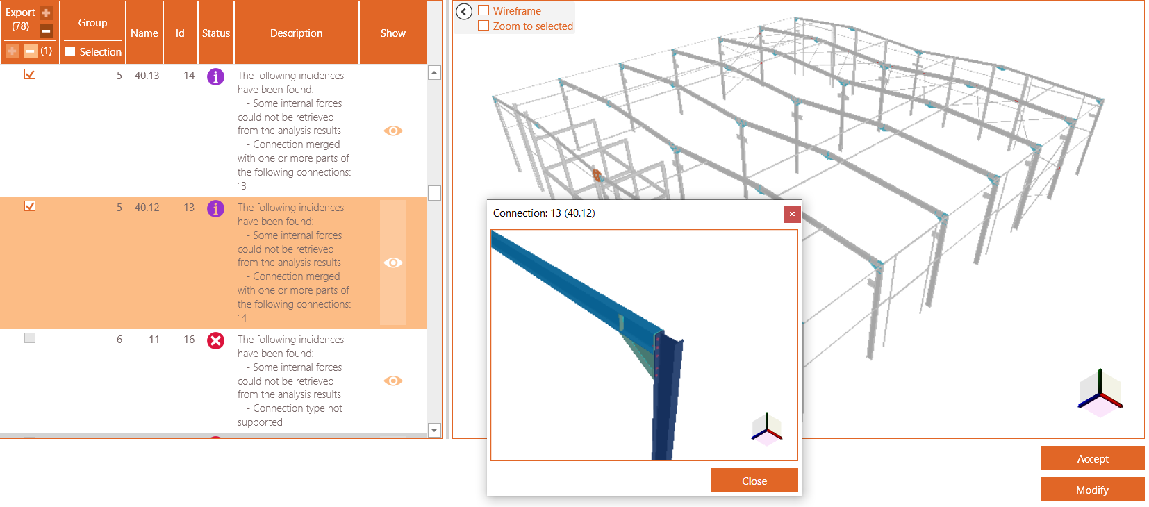
Use the eye button in the ‘Show’ column to see a detailed popup window of the connection.
Possible descriptions are
- Some internal forces could not be retrieved from the analysis results
No (or not all) internal forces are present from the source software. - The connection is identical to connection(s) {IDs} and therefore has been grouped
Identical connections will be treated as one connection. You must only calculate the connections one, with envelope forces. - Connection merged with one or more parts of the following connection: {ID}
The connection is merged with other one to create a more complex connection (e.g. two shear connections to beam-column are merged to design a double-sided shear connection) - Connection divided into <….> connections
A complex connection has been split up into smaller PowerConnect connections - The connection bars/plates with following ID’s could not be recognized: {IDs}
The connection is recognized and can be calculated with PowerConnect, execpt for these bars/plates, with given Ids - Connection type not support
This connection configuration cannot be calculated by PowerConnect, so it will not be transferred.
Click ‘Accept’ to continue to PowerConnect.
If you have chosen to open the model directly in PowerConnect, you will get a notification in PowerConnect on the right side. You can now choose to load the model or to delete it (by using the ‘x’).

1. Preparation in Tekla Structures
The transfer is based on the analytical model. So in Tekla Structures, you need to create an analytical model first. The quality and coherence (connection between elements) of the analytical model is not relevant, as PowerConnect uses the physical model.
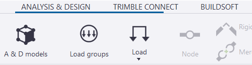
In the top ribbon, go to the tab ‘Analysis & Design’ and click the ‘A & D models’ command
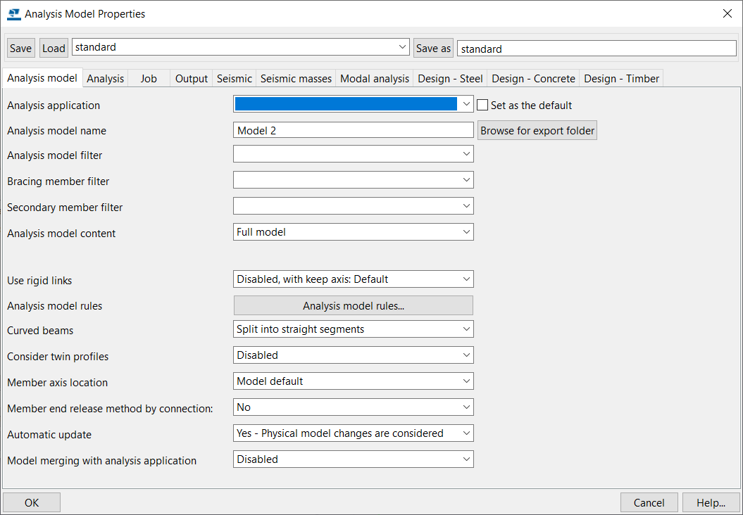
Next create a New analysis model – a Analysis Model Properties window will pop-up. The analysis model content should be ‘Full model’ – unless you want to start selecting element per element.
2. Send model from Tekla Structures to PowerConnect
2.1 From Tekla Structures to BIM Expert
There is more than 1 way to send models from Tekla Structures to BIM Expert. You can either start from
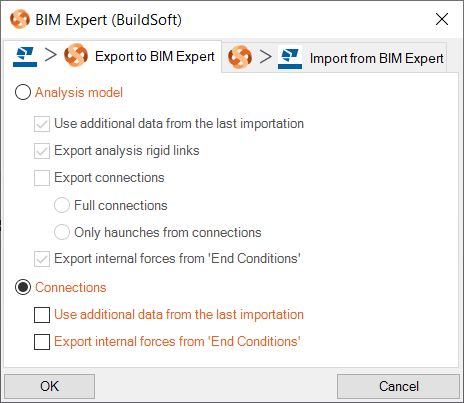
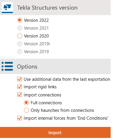
Click the BIM Expert icon to launch the transfer. Next you need to select what items to include, in addition to the Analysis model:
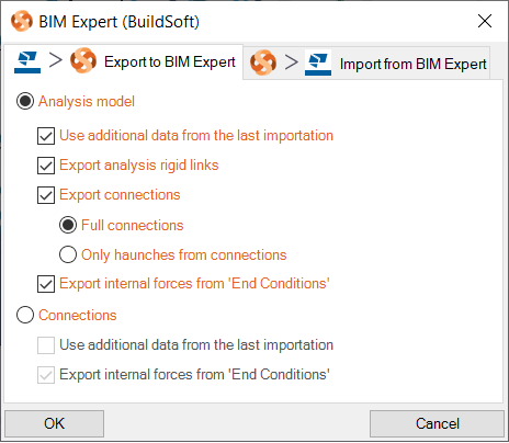
- Additional data: data that came from a previous transfer, but is not supported by Tekla Structures. This information is kept and can now be taken along in the current transfer (e.g. seismic information, soil layers, …)
- Rigid links
- Connection: full or only haunches
- Internal forces from ‘End Conditions’. The End Conditions tab can be found in the element’s UDA (User Defined Attributes):
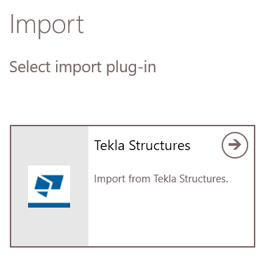
Alternatively, you can start in BIM Expert: click ‘Model > Import’ and select the Tekla Structures plugin. Choose the Tekla Structures version and what elements to import (see above).
No matter the way you have chosen, BIM Expert will now take over.
2.1.1 Settings
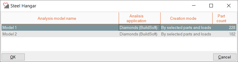
If you have more than one analytical model in Tekla Structures, you need to select the analysis model that you want to transfer
Next, the Tekla Structures sections and materials must be mapped with BIM Expert’s section and material database. BIM Expert will try to find as many automatic mapping matches as possible. In case all sections and materials find a match, you will not see any dialogs for mapping.
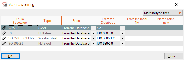
2.1.2 Material mapping
In case you have turned off the option to reduce dialog windows, you might see a material mapping dialog for mapping unknown materials. In the ‘reduce dialog window’ case, unknown materials will be added as new.
Database materials such as steel (e.g. S235, ASTM-Grades), concrete (e.g. C25/30, M50) and timber (e.g. C24, D50, GL28c) are mapped automatically. In some cases, the match is not automatically found, because the name differs (Concrete grade C25 instead of Concrete grade C25/30). In that case, you can select the correct material from the database.
Tip: When searching an item in the database, type the first letters of the name to find it more quickly.
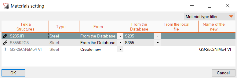
If you cannot find a suited counterpart in the BIM Expert database, the material can be added as new.
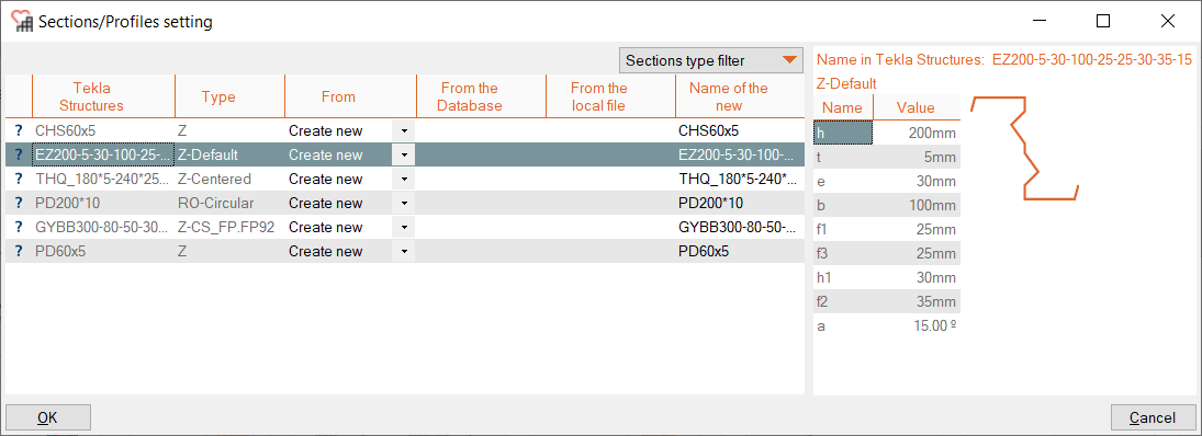
2.1.3 Section mapping
In case you have turned off the option to reduce dialog windows, you might see a section mapping dialog for mapping unknown sections. In the ‘reduce dialog window’ case, unknown sections will be added as new.
Database sections (such as I, H, UB, UC, W, C, U, O, ☐ and L sections) are mapped automatically. In some cases, the match is not automatically found, because the name differs (e.g. name is HEB300 – S235 instead of HEB300). In that case, you can select the correct cross-section from the database.
Tip: When searching an item in the database, type the first letters of the name to find it more quickly.
Parametric sections (e.g. rectangles, circle, trapezium, …) and user defined sections are not in the database. They should always be added as new.
2.1.4 Connections and component bundles
In case you have chosen to export connections and there are connections in the model, BIM Expert will now start the connection conversion.
If you have turned off the option to reduce the dialog windows, you will get an overview of all connections components in the model and the possibility to bundle components.
In this window you can do 2 things:
- Select the connections to be included in transfer, via the checkbox in the ‘Accept’ column
- Bundle connection components into larger complex connection groups:
- Position this window in a corner of your screen, because once you start adding groups, the window position is locked.
- Click ‘Add group’ to select the components.
- Select the components by clicking the component arrow. All components should logically be around a single node of course.
- Confirm the selection with the middle mouse button.
- The group is now listed with the reference ids of the individual components.
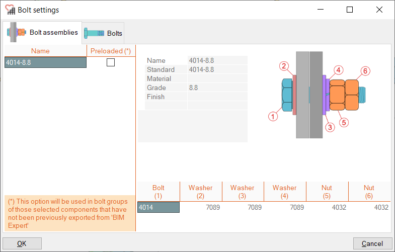
If there are materials of bolt elements to be mapped, they will appear in the next pop-up window.
The model is now in BIM Expert.
2.2 From BIM Expert to PowerConnect
In the Model tab, select ‘Export’. Next, choose the destination software, namely PowerConnect. Click ![]() to continue.
to continue.
2.2.1 Settings
You can choose to either
- save the model as *.bpc-file
- send the model to the current open PowerConnect instance – you see all open instances of PowerConnect
Select your choice and click ![]() to continue.
to continue.
2.2.2 Automatic detection of connection components
BIM Expert automatically detects existing connection components in the model. You get an overview of all found connection components and whether they can be transferred to PowerConnect.
Use the eye button in the ‘Show’ column to see a detailed popup window of the connection.
Possible descriptions are
- Some internal forces could not be retrieved from the analysis results
No (or not all) internal forces are present from the source software. - The connection is identical to connection(s) {IDs} and therefore has been grouped
Identical connections will be treated as one connection. You must only calculate the connections one, with envelope forces. - Connection merged with one or more parts of the following connection: {ID}
The connection is merged with other one to create a more complex connection (e.g. two shear connections to beam-column are merged to design a double-sided shear connection) - Connection divided into <….> connections
A complex connection has been split up into smaller PowerConnect connections - The connection bars/plates with following ID’s could not be recognized: {IDs}
The connection is recognized and can be calculated with PowerConnect, execpt for these bars/plates, with given Ids - Connection type not support
This connection configuration cannot be calculated by PowerConnect, so it will not be transferred.
If no connections are found, you will see

2.2.3 Add connections manually via Connection Assembler
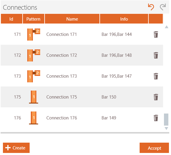
You can make your own connections by clicking ‘Modify’ (see image above).
In the next window, you see on the left hand side the BIM Expert model. In this window you see the regular scroll, 3D orbit and pan functions. On the right hand side, there is on top an overview of created connections and at the bottom, the ‘Create’ button to make new connections.

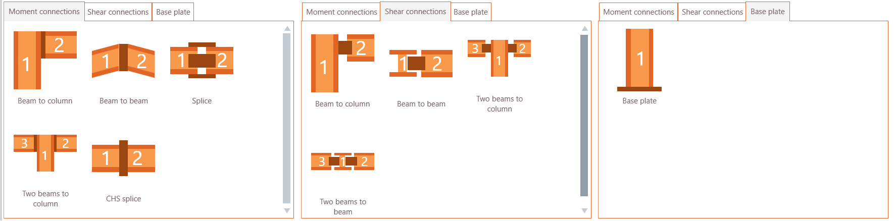
In the next step you choose the connection type
- Moment connections: beam-column, beam-beam, splice, beam-column-beam or CHS splice
- Shear connections: beam-column or beam-beam, beam-column-beam or beam-beam-beam
- Base plate connections
After selecting for example ‘Beam to column’ you select the column and next the beam element from the 3D image on the left hand side. Click once on the column element and next on the beam element. BIM Expert will list and indicate which connections are possible:
- Beam to column flange > possible, and marked with

- Beam to column web > not possible, and not marked – you can click the orange arrow
 at the end to fold out the details and see why this connection is not possible.

On clicking ‘Create’, the connection is added to the list of connections on top. Having selected the beam-column type, you can now continue making this type of connections, until you click ‘Change pattern’.
When the connection definition is finished, you click ‘Close’ and ‘Accept’ to continue to PowerConnect.
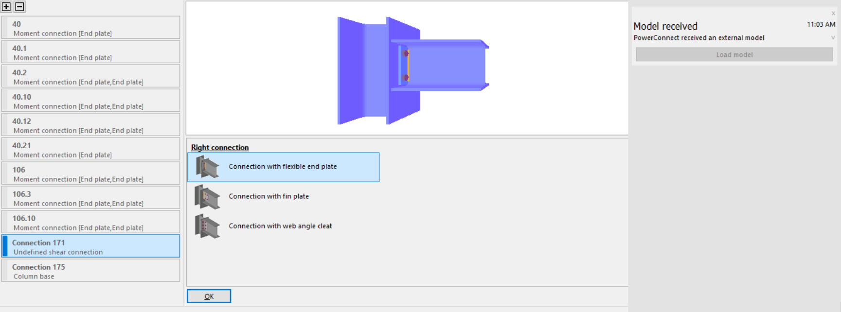
If you have chosen to open the model directly in PowerConnect, you will get a notification in PowerConnect on the right side. You can now choose to load the model or to delete it (by using the ‘x’).
3. Final steps in PowerConnect
All connections will appear in the node list on the left side (as from PowerConnect 2021). Remember that all identical connections will be grouped as 1.
Connections made with the Connection Assembler might appear with a red bar and as ‘Undefined’. The connector type must be chosen (e.g. end plate, shear plate, welded, angles etc)
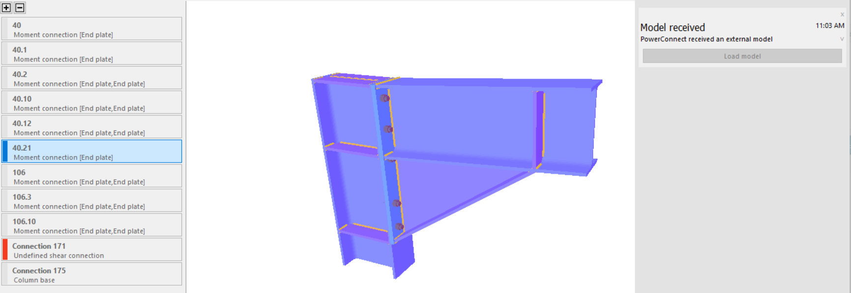
Click on this connection to set the connector.
If no loads or internal forces were transferred, you should add loads in PowerConnect, in order to have a proper design of the connections.
