This article explains how to send one or more ETABS nodes to Idea Statica Connection, using BIM Expert.
1. Preparation in ETABS
Make sure the model is calculated and that elastic results are available.
2. Send the ETABS model to Idea StatiCa Connection
2.1 From ETABS to BIM Expert
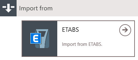
In the Model tab, select ‘Import’. Next, choose the source software manufacturer, namely ‘Computer and Structures, Inc’ (CSI) . Click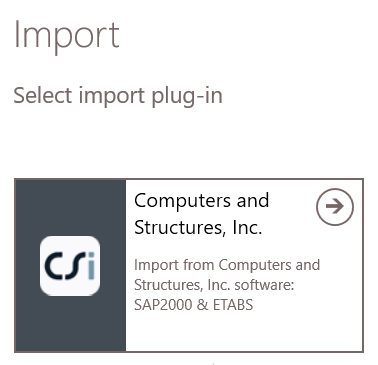 Choose ‘ETABS’.
 Alternatively, models can be sent to BIM Expert directly within ETABS (Tools > BIM Expert), but you first need to add BIM Expert as a plug-in to ETABS.
2.2.1 Settings
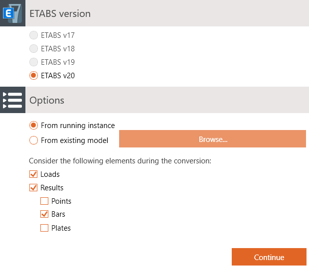 Select your ETABS version, and were the model is coming from:
- A running instance – that means, the model is currently open in ETABS
- An existing model – click ‘Browse… ‘ to open your file browser, go to the model location and select the model (an .edb file)
2.2.2 Material mapping
Database materials such as steel (e.g. S235, ASTM-Grades), concrete (e.g. C25/30, M50) and timber (e.g. C24, D50, GL28c) are mapped automatically. In some cases, the match is not automatically found, because the name differs (S355-link instead of S355). In that case, you can select the correct material from the database. Tip: When searching an item in the database, type the first letters of the name to find it more quickly.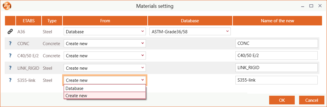
2.1.3 Section mapping
Database sections (such as I, H, UB, UC, W, C, U, O, ☐ and L sections) are mapped automatically. In some cases, the match is not automatically found, because the name differs (e.g. name is HEB300 – S235 instead of HEB300). In that case, you can select the correct cross-section from the database. Tip: When searching an item in the database, type the first letters of the name to find it more quickly. Parametric sections (e.g. rectangles, circle, trapezium, …) are not in the database. They should always be added as new.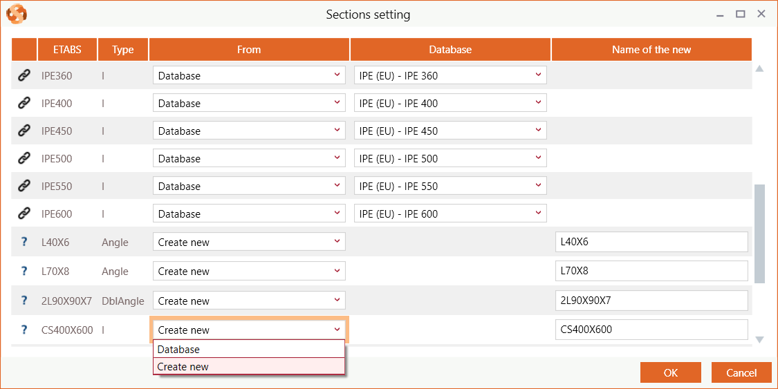
2.1.4 Loads mapping
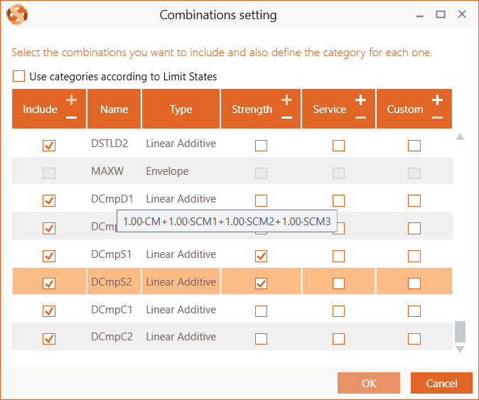
If you opted to consider the loads during export, the ETABS load combinations need to be categorized. Each valid ETABS combination must be categorized into Eurocode or American combinations. Use the checkbox ‘Use categories according to Limit States’ to switch between European and American combination categories.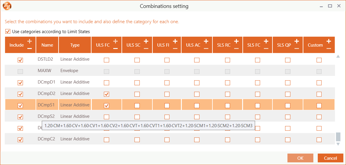
- Eurocode Limit States
- ULS – Ultimate Limit State Combinations: Fundamental (FC), Seismic (SC), Fire (FI) or Accidental (AC)
- SLS – Serviceability Limit State Combinations: Rare (RC), Frequent (FC) or Quasi-Permanent (QP)
- Custom
- American
- Strength
- Service
- Custom
2.1.5 Reporting
In case of severe incidences, you get a report of the incidences. It usually concerns load cases or element behavior that are not supported by BIM Expert. Click ‘Continue’ to proceed anyway.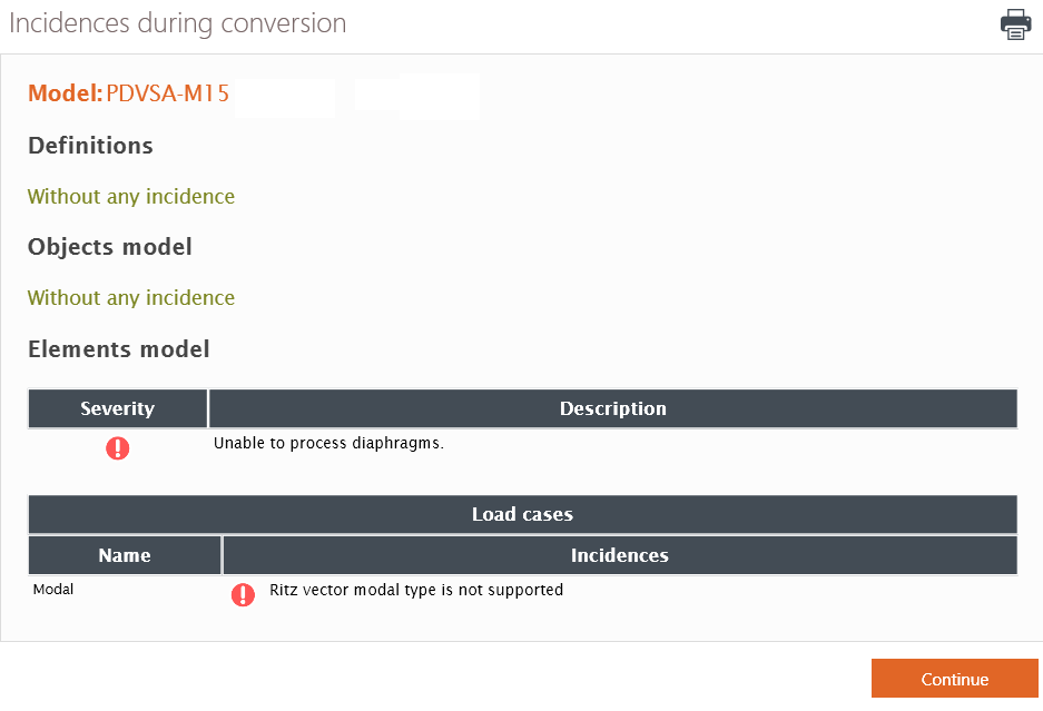 The model is now in BIM Expert.
2.2 From BIM Expert to Idea StatiCa Connection
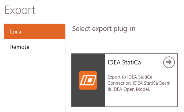
In the Model tab, select ‘Export’. Next, choose the destination software, namely Idea StatiCa. Click ![]() to continue.
to continue.
2.2.1 Settings
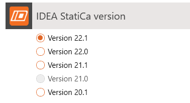
2.2.1.1 Version
Select the desired version of Idea StatiCa.
2.2.1.2 Model type
Choose between model types analysis or physical:

- The analysis model will only send independent analytical bars, as defined in the analytical model:
- When bars are continuous in reality and grouped into a physical group, this is ignored.
- Existing connections (e.g. from Tekla Structures, Revit or PowerConnect) are also ignored. Only the analysis members will remain. All physical elements (bolts, welds, connection plates, … ) will be ignored in the transfer.
- The physical model will send physical elements, that is
- Continuous bars (if properly grouped)
- Connections including all physical elements (bolts, welds, connection plates, … ). Connections are always in the physical model defined.
If you choose physical model, it is recommended to opt for ‘Use data from analysis model’, as this will use the load and result information from the analysis model.
It is good practice to check ‘Export loads’ and Export results’ unless you want to define the loads again in Idea StatiCa Connection.
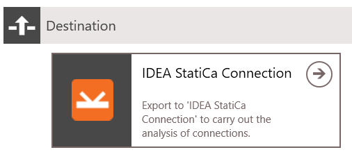
2.2.1.3 Destination
Select the destination ‘Idea StatiCa Connection’.
2.2.2 Select nodes and connections
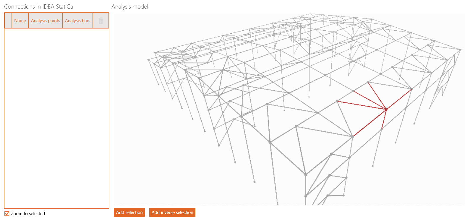
In the next window you get an overview of the model, where nodes and connections can be selected to be transferred. On the left side, ‘Connections in Idea StatiCa’ holds a list with all connections to be sent to Idea. The list is empty by default.
Depending on the choice of model (analysis or physical) and whether there are physical connections present in the model, this window can have different layouts.
You will see the analysis ‘bar’ model, with square nodes at the intersection points. If there are physical connections present in the model, you will also see the physical model and a list of recognized connections.
Click on a node in the Analysis model to select all connected bars (shown in red) and hit ‘Add selection’ to add them to the list. Already added nodes will be displayed in blue.
If physical connections are present, you can also select these nodes from the physical model, but only the ones that are already defined in the list. When you select a node, the physical model will zoom to the selected item.
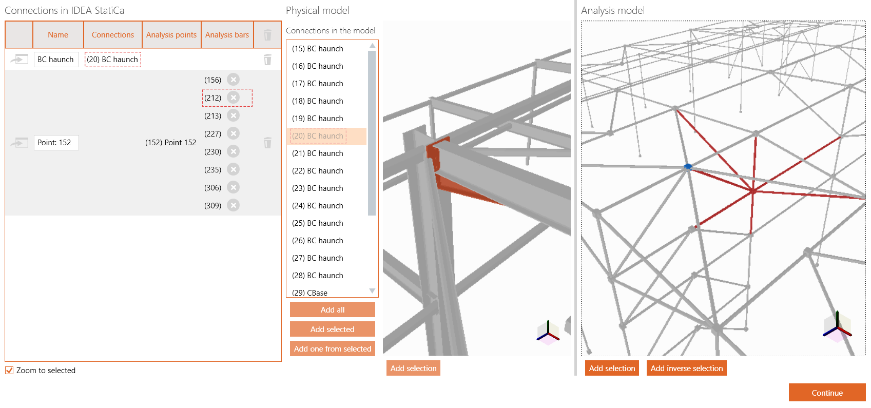
You see will the physical model, with all cross-section drawn.
Add a connection by either:
- Selecting one or more existing physical connections from the list and click ‘Add selected’
- Selecting an existing physical connection from model, by clicking one the connection part (e.g. haunch, end plate, bolts, … ) and click ‘Add selection’. The whole connection will be highlighted in red.
- Selecting multiple physical bars:
- First click on an empty white space to ensure nothing is selected
- Select physical bars (highlighted in red) and click ‘Add selection’

Hit ‘Continue’ to continue the transfer to Idea StatiCa.
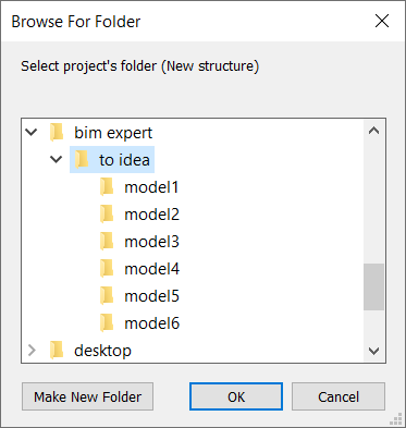
2.2.3 Saving the model
Choose a folder to save the conversion files (IOM etc). We recommend to have a separate BIM Expert folder, where all your models are stored.
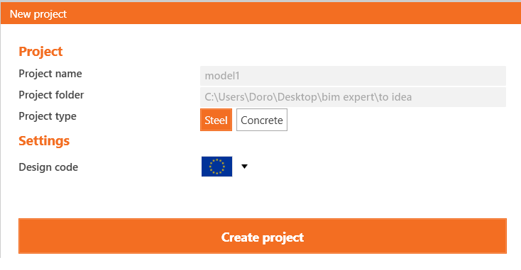
2.2.4 Open the model in Idea Checkbot
Idea Checkbot will launch automatically. A ‘New’ tab, a new project is proposed and the project name and project folder are filled out accordingly. Click ‘Create project’ to start.
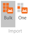
2.2.5 Load the nodes
Click ‘Import > Bulk’ to load all nodes. Depending on the number of nodes selected and the amount of results in model, this can take a while.
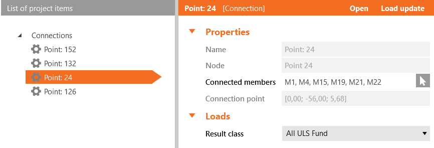
Select a connection from the list of project items and click ‘Open’ to open it in Idea StatiCa Connection.
3. Final steps in Idea StatiCa Connection
In case you have sent the analytical model, you need to add bolts and connection plates to build up your model.
In case you have sent the physical existing connections, you will see the already defined connection. Other physical bars will need to be completed with bolts, welds, connection plates etc.
