What is a rigid link
A rigid link is an infinitely stiff element that transfers forces. It displaces (moves) as a rigid body (it cannot deform). Subsequently a rigid link has no cross-section or material. It’s not possible to show the results in a rigid link, although they contain forces!
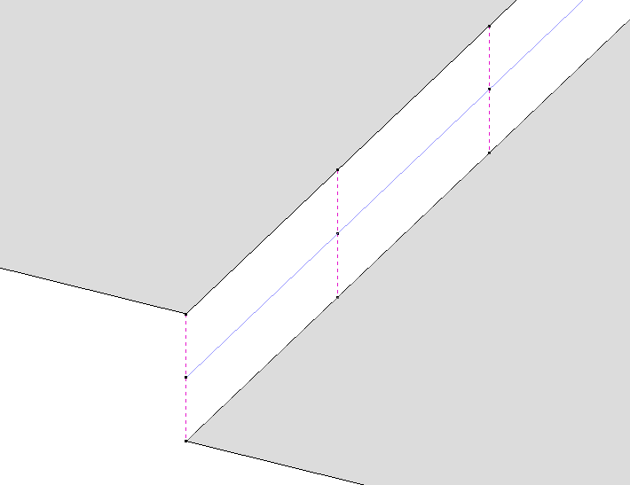
In Diamonds, rigid links are represented by a dashed pink line.

Rigid links are used to simulate the force transfer between elements (that can be bars or surfaces) that cannot be simulated with the pre-existing functions: ![]() ,
, ![]() and
and ![]() .
.
For example: to simulate a beam (blue line) connecting plates on a significant different level (see image above).
How to make a Rigid link
- Select the bars you want to define as a rigid link.
- Click on
 . The rigid link is created.
How to remove a rigid link
- Select the relevant rigid links.
- Assign a random cross-section & material to the rigid links. This can be done for example with using the steel cross-sections library
 .
. - The rigid links are transformed into a regular bar.

