
What does an eccentricity do?
The purpose of eccentricities is to have the behaviour of a calculation model (= Diamonds model) correspond as closely as possible with the real behaviour of the structure. The purpose of eccentricities is NOT to give the calculation model the same appearance as the architectural model.
Eccentricities affect how the stiffness of the elements (plate and beam) are assembled:
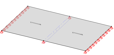
- When the beam has no eccentricity (see Model 1 below): the rigidity of the plate will locally be increased with the rigidity of the beam (= the sum of both rigidities).
- When the beam has an eccentricity (see Model 2 below): the beam and plate will work together as a T-section. The rigidity of this composed section will be higher than the sum of both rigidities.
In order to illustrate this, we compare the load distribution towards the end support lines and the centreline in 4 beam-plate models (9 x 5.5m, one way slab of 0.2m thick, simply supported on two opposite sides, 10kN/m²).
- Model 1: a beam in the middle, not eccentric
- Model 2: same beam in the middle, eccentric
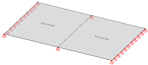
- Model 3: no beam in the middle (or a beam with a very low stiffness in comparison to the plate)
- Model 4: a support line in the middle. The plates will behave as perfectly continuous.
Result:
| Model 1 45% to the support lines left and right 55% to the point supports | Model 2 40% to the support lines left and right 60% to the point supports |
 |  |
| Model 3 87% to the support lines left and right 13% to the point supports | Model 4 40% to the support lines left and right 60% to the point supports |
 |  |
Conclusion:
- As expected, the beam in Model 2 acts stiffer than the one in Model 1. The beam in Model 2 draws more force to itself, then the beam in Model 1.
- With increasing beam stiffness, Models 1 and 2 will behave like Model 4.
With decreasing beam stiffness, Models 1 and 2 will behave like Model 3.
- The percentages may vary depending on the length/width radio of the plates and the plate type (one way slab, two way slab, preslabs, …).
When do eccentricities cause normal force?
To investigate when eccentricities cause normal forces, we create a beam model with the following data: 200x500mm, 5m span, dead weight + 15kN/m permanent load, eccentric so that the axis of the beam coincides with the bottom of the beam. We consider an isostatic and hyperstatic support.
| Wire frame representation Solid representation |  |
Results for the internal forces:
| Bending moment |  |
| Shear force |  |
| Axial force |  |
Conclusion:
- Normal forces only arise when the beam element is hyperstatic. Normal forces do not occur when the beam is isostatic.
Unfortunately, most structures are hyperstatic, and normal forces often occur due to eccentricities. - If we perform the same exercise for a suspended beam (the axis of the beam coincides with the top of the beam), we arrive at the same conclusion.
How large is the normal force in an eccentric beam?
A worked example can be found in the validation examplees.
How does the force acting in an eccentric beam compare to that in a non-eccentric beam?
When we place a beam eccentric in relation to a plate, the beam axis shifts with respect to the axial plane of the plate. This creates a completely different force distribution:
- When the beam is not eccentric in relation to the plate, both are working in bending. There’s not axial force in the system.
- When the beam is eccentric in relation to the plate, both bending and axial force will arise. If the beam is under the plate, there (usually) will be compression in the platen and traction in beam. If the beam is above the plate, there (usually) will be traction in the plate and compression in the beam.
Although the force distribution is different in both systems (with or without eccentricities), the total amount of bending moment remains the same. To illustrate this, we model a T-section in 3 different ways: “Geometry + Loads” describes the geometry and the loads of the different models and “Comparison internal forces” compares the internal forces. In this paragraph we come back to these models again regarding the reinforcement and cracked deformation.
Geometry + loads
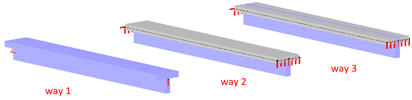
| Way 1 | Way 2 | Way 3 | |
| Cross-section beam | T cross-section with dimensions: B=200mm H=700mm bf=1000mm hf=200mm | R cross-section with dimensions: B=200mm H=500mm | R cross-section with dimensions: B=200mm H=700mm |
| Cross-section plate | none | B=1000mm | H=200mm |
| Eccentricity | none | Upper side beam = lower side plate e=0,35m | Upper side beam = upper side plate e=0,25m |
| Dead load | 25kN/m², which comes to a line load of 25kN/m for Way 1 (T-beam is 1m wide). | ||
Comparison internal forces
We look at the internal forces in the load group ‘dead loads’ (not ULS FC) because Way 3 contains a little more self-weight than the other two.
| Way 1 | Way 2 | Way 3 | |
| Bending moment in the beam | 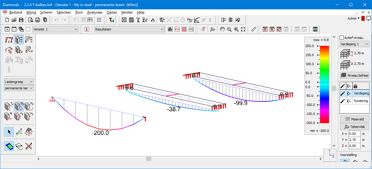 | ||
| Mean bending moment in the middle of the plate | 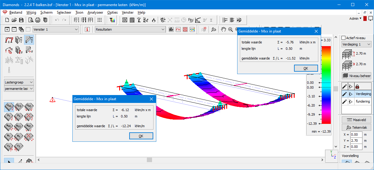 | ||
| Axial force in the beam | 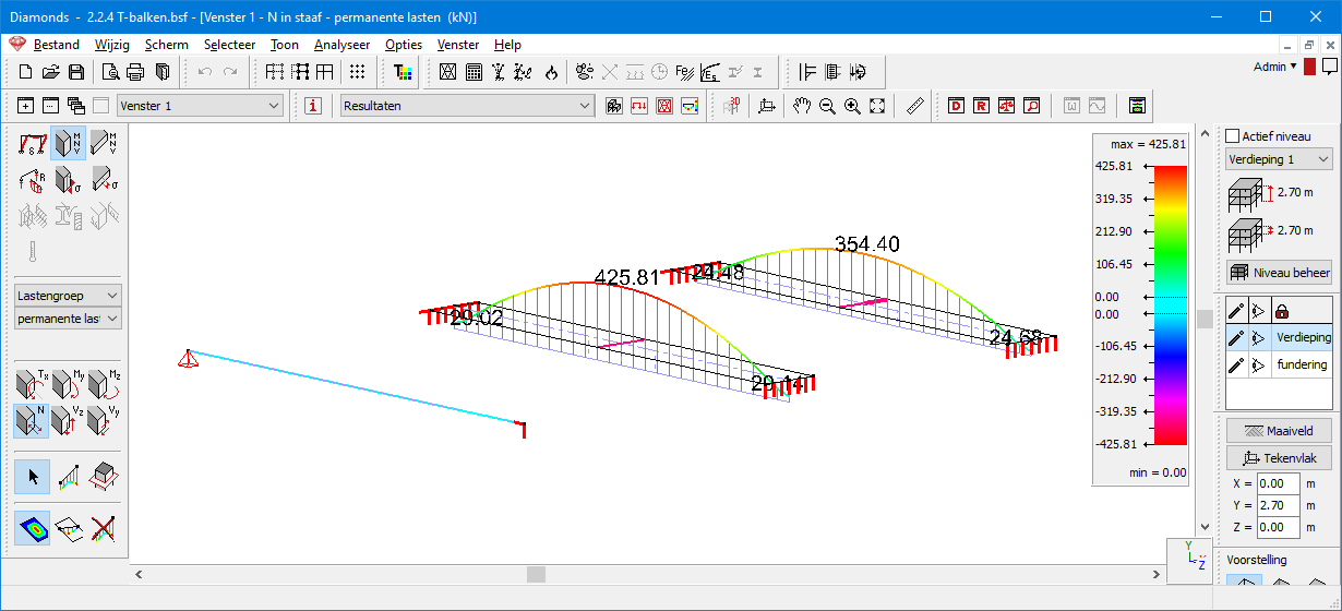 | ||
| Mean axial force in the middle of the plate | 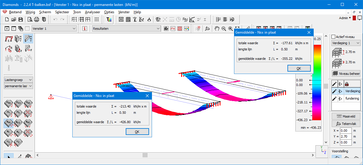 | ||
| Total bending moment | 200kNm | 38.7kNm + 12.2kNm + 426.8kN x 0.35m =199.9kNm | 99.9kNm + 11.5kN + 345.4kN x 0.35m =199.9kNm |
Conclusion: the total amount of bending moment in the system is the samen. It’s only being distributed in a different way.
Collaboration concrete beam – concrete plate
Aim
Consider the 2D plate model below (pre-slabs 200/50, beams R150/350, 15kN/m²). The beam-plate connections can be made in various ways on site:
- continuous plate, simply placed on the beam
- discontinuous plate, simply placed on the beam
- beam and plate are poured together. Both beam and plate will work together as a whole.
This implementation determines the modelling in Diamonds, because the modelling must describe the real behaviour of the structure as well as possible.

In Diamonds
This section looks at how the different ways of execution are modelled in Diamonds: with and without eccentricities. Working with or without eccentricities has advantages and disadvantages. You will notice that one situation lends itself better to the use of eccentricities than another.
Continuous versus discontinuous
Before getting started with the different cases, we’d like to illustrate the difference between a ‘continuous’ and a ‘discontinuous’ plate.
- In a ‘continuous’ plate, the reinforcements extends over different plate surfaces.
In other words, all internal forces can be transferred between the different plate surfaces. - In a ‘discontinuous’ plate, the reinforcements does not extend over different plate surfaces.
In other words, no internal forces can be transferred between the different plate surfaces.
This continuous or discontinuous behaviour cannot be detached from the geometry/loads on the plate. Diamonds calculates the reinforcement based on the internal forces in the element. And the internal forces follow from the geometry (the boundary conditions!) and the loads.
On a discontinuous slab, there are hinge lines on the slab edges. These hinge lines prevent moment from being transferred between the different plate surfaces. These hinge lines therefore apply to both the top and bottom reinforcement.
On a continuous slab, there are no hinge lines on the slab edges. All force action can be transferred.
Within Diamonds, the precondition ‘continuous upper reinforcement and discontinuous lower reinforcement’ (or visa versa) does not exist. There is only ‘continuous upper and lower reinforcement’ or ‘discontinuous upper and lower reinforcement’.
If it follows from the reinforcement calculation that at a slab edge: continuous upper reinforcement, discontinuous lower reinforcement, then this is a consequence of the loads on the slab. Not the result of a boundary condition that were applied, because there are no special boundary conditions that can force that behaviour.
Case 1: continuous plate, simply supported on beam
The plates in the 2D plate model are designed as discontinuous, simply supported by the central beams. For the support of the plates on the edge beams, see Case 2.
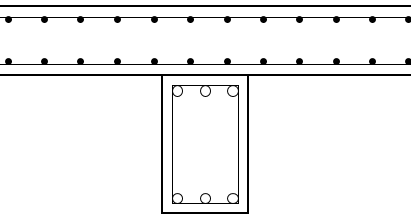
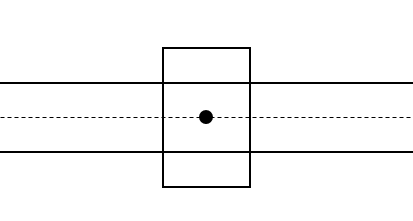
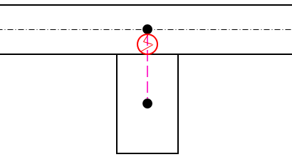
The table below lists the assumptions made for each model.


Result:
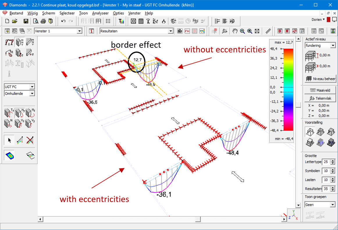
- The bending moment in the field is indeed comparable.
- Against all expectations, a retaining moment occurs in the model without eccentricities.
This moment occurs because the plates can still transfer forces to the beam on one hand, and because of the compatibility of deformations on the other hand.
With the compatibility of deformations means the following: the plate bears in two directions, so it also deforms in two directions. The deformation that the plate undergoes along the four orange cut lines, must remain compatible. And this is not always that easy, resulting in ‘abnormalities’ in the internal forces.
‘Abnormalities’ is between quotation marks, because the border effects are something you don’t expect, but they are normal in this type of modelling. The only approach where they can be eliminated, is 1D modelling and simple load descent like in hand calculations. But hand calculations make a lot of simplifications, in a way that they are sometimes not comparable to the reality.
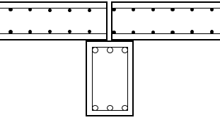
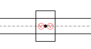
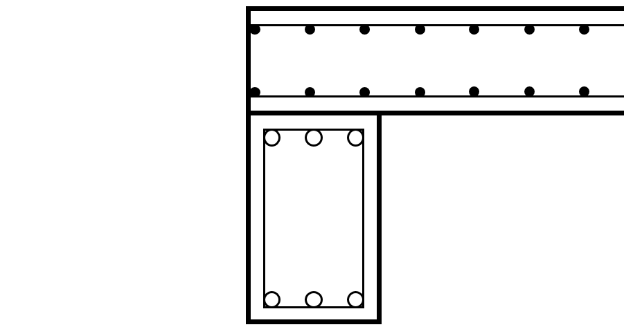
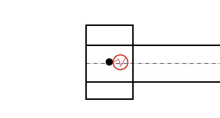
Case 2: discontinuous plate, simply supported on beam
The plates in the 2D plate model are designed as discontinuous, simply supported by the central beams. The plates in the 2D plate model are designed as simply supported by the central beams by the edge beams.
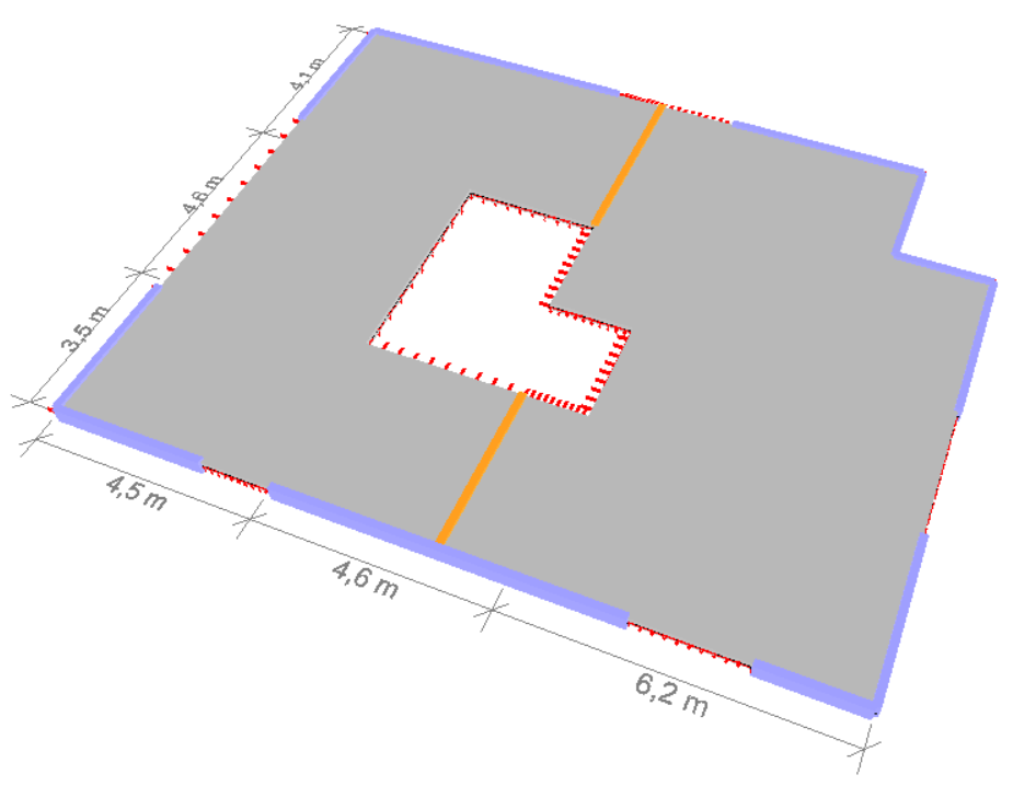
The table below lists the assumptions made for each model.
| Case 2 reality: Discontinuous plates, simply supported on beam | Diamonds | |||
Without eccentricities License 2D slabs required License 2D slabs required |
With eccentricities License 2D slabs + 2D plates required |
|||
 |
 |
 |
||
 |
|
 |
||

|
– | |
Top beam = top plate | |

|
Beam height = h | |
Beam height = h | |
 |
Allow only transfer of V along the plate edges | |
Allow only transfer of V along the plate edges | |
 |
Disable moment transfer on bar ends if you want simply supported behaviour. | |
Disable moment transfer on bar ends if you want simply supported behaviour. | |
 |
|
|
|
|
| Reinforcement in plates and beam should be placed. | Reinforcement in plates and beam should be placed. | |||
Result:
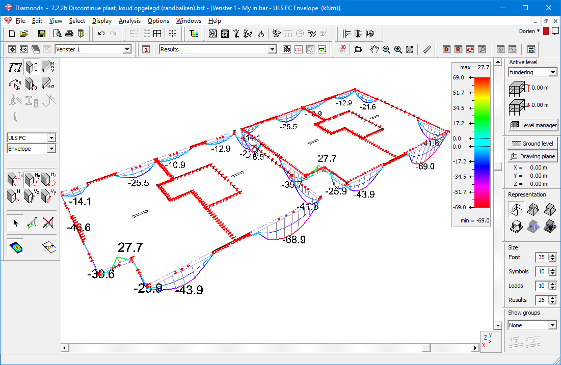
- The bending moment in the field is indeed comparable.
- Both models now contain retaining moments. Although the hinges prevent the transmission of internal forces between the plates and the beam, the plate itself remains bearing in two directions. So here, it is the compatibility of the deformations that causes the retaining moments.
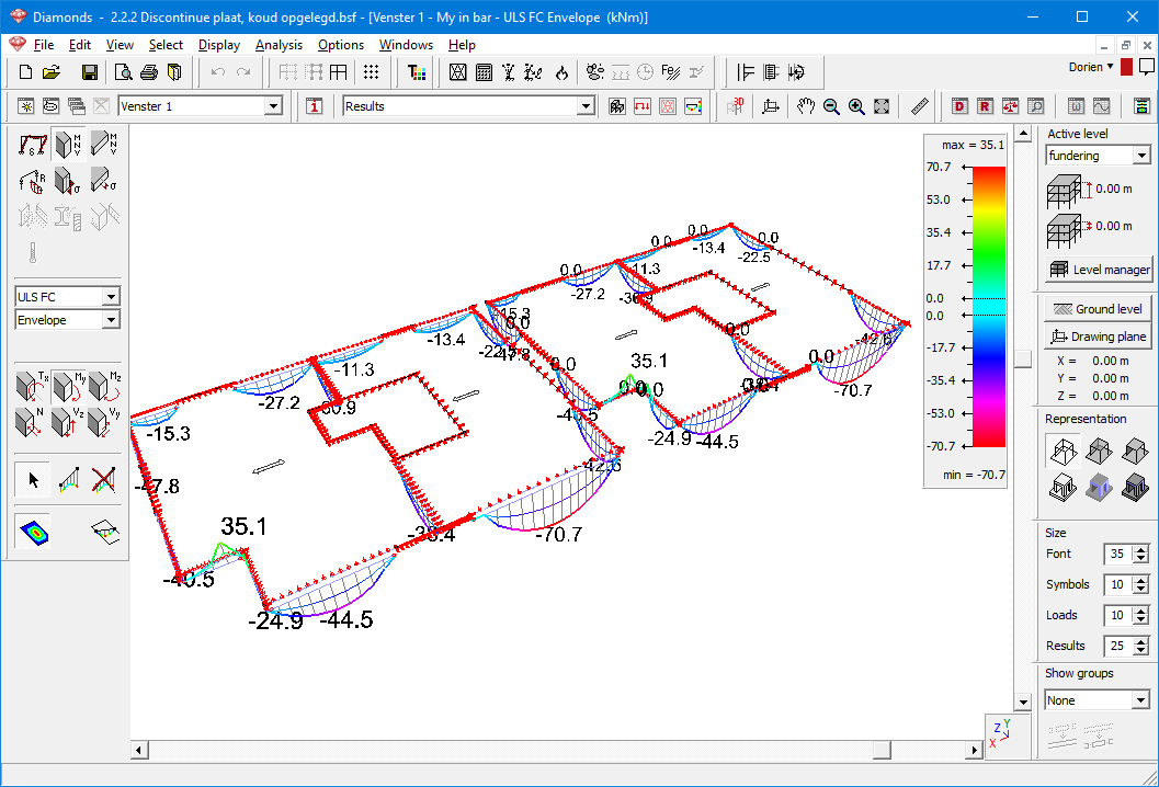
Note: for beams along the edge of a plate, it doesn’t matter if you apply the hinges on the border of the plate or on the rigid links. Both give similar results.
Case 3: beam and plate poured together
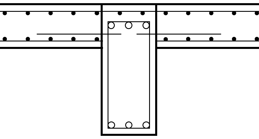
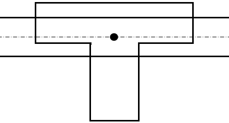
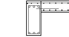
The plates in the 2D plate model are poured together with the central and edge beams. Both beam and plate will work together as a whole.
The table below lists the assumptions made for each model.
| Case 3 reality: Beam and plate poured together | Diamonds | |||
| Without eccentricities License 2D slabs required |
With eccentricities License 2D slabs + 2D plates required |
|||
 |
 |
 |
||
 |
 |
 |
||
|
– | |
Top beam = top plate | |
|
|
|
Beam height = H | |
 |
|
|
|
|
| Reinforcement in plates and beam should be placed. | Reinforcement in plates and beam should be placed. | |||
 > uncheck the checkboxes before the buckling lengths
 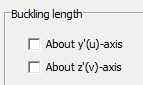 ).
).In this modelling, it hard to compare the internal forces. Both models do not have the same self-weight and axial forces will occur in the eccentricity model. So, the cracked deformation (+ creep + extend theory to axial forces) is used to compare the stiffness between the two models.
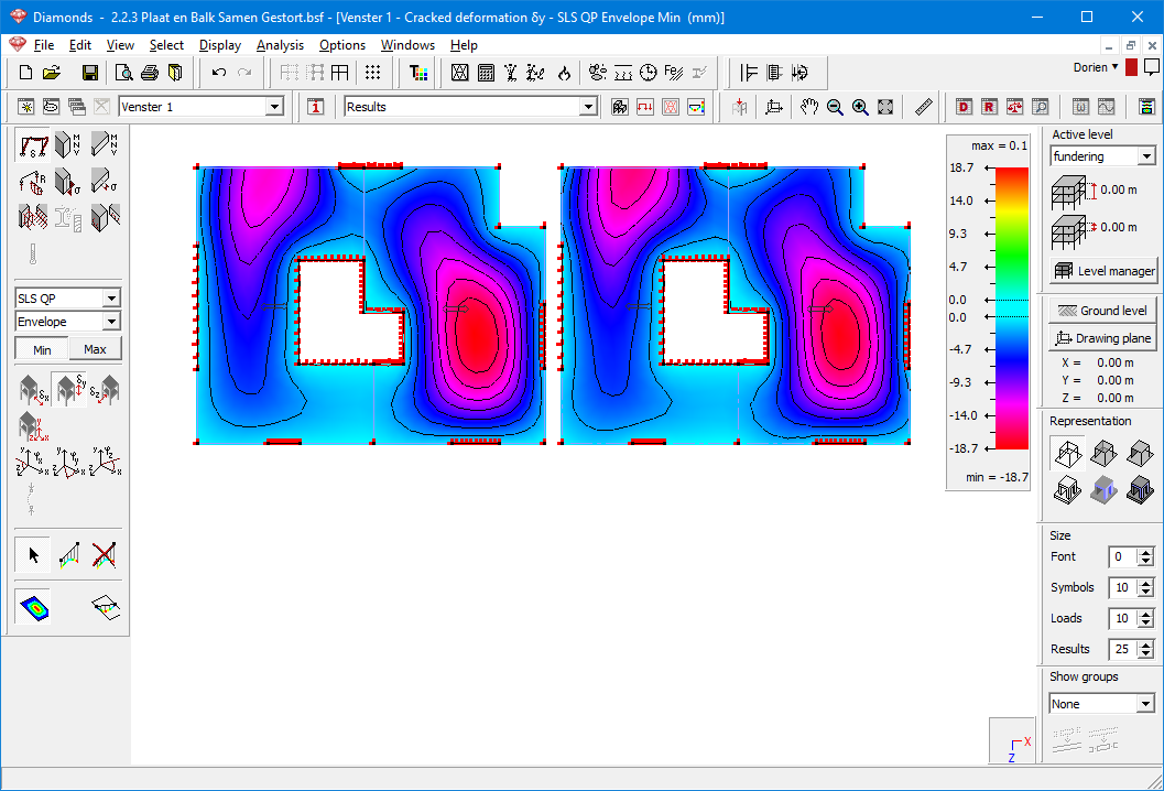
In the image above we see that the 2 modelling approaches (with or without eccentricities) give similar results, yet not entirely the same. This is because it is hard to estimate/calculate the effective widths of the T- and L-sections.
Out of curiosity, let’s add a model in which non-eccentric R-sections are used. While we had a maximum cracked deformation after creep of 18,7mm (see previous image), we now find a maximum of 31,2mm. Confirming the statement that using a non-eccentric R-section to simulate beam-plate poured together will underestimate the stiffness of the beams.

Why Upper side beam = upper side plate for Case 3?
In case 3 upper side beam = upper side plate was chosen. As a result, the plate thickness must be added to the beam height, resulting in additional self-weight. Something that we (understandably) experience as contradictory. But that extra beam height is necessary to develop sufficient stiffness. We again include the beam models from this paragraph:
- Way 1 from “Geometry + loads” corresponds to Case 3 modelled without eccentricities.
- Way 3 from “Geometry + loads” corresponds to Case 3 modelled with eccentricities
( = plate thickness added to beam height = the modelling that feels a bit contradictory) - Way 2 from “Geometry + loads” corresponds to Case 3 with eccentricities
( = plate thickness NOT added to beam height = the modelling we would expect at first glance)
The purpose of Diamonds is to design, therefore we focus on the reinforcement and cracked deformation. We will recalculate the model multiple times and look at how the reinforcement amounts and cracked deformation evolves in the 3 different models:
| Way 1 | Way 2 | Way 3 | |
Elastic deformation  | 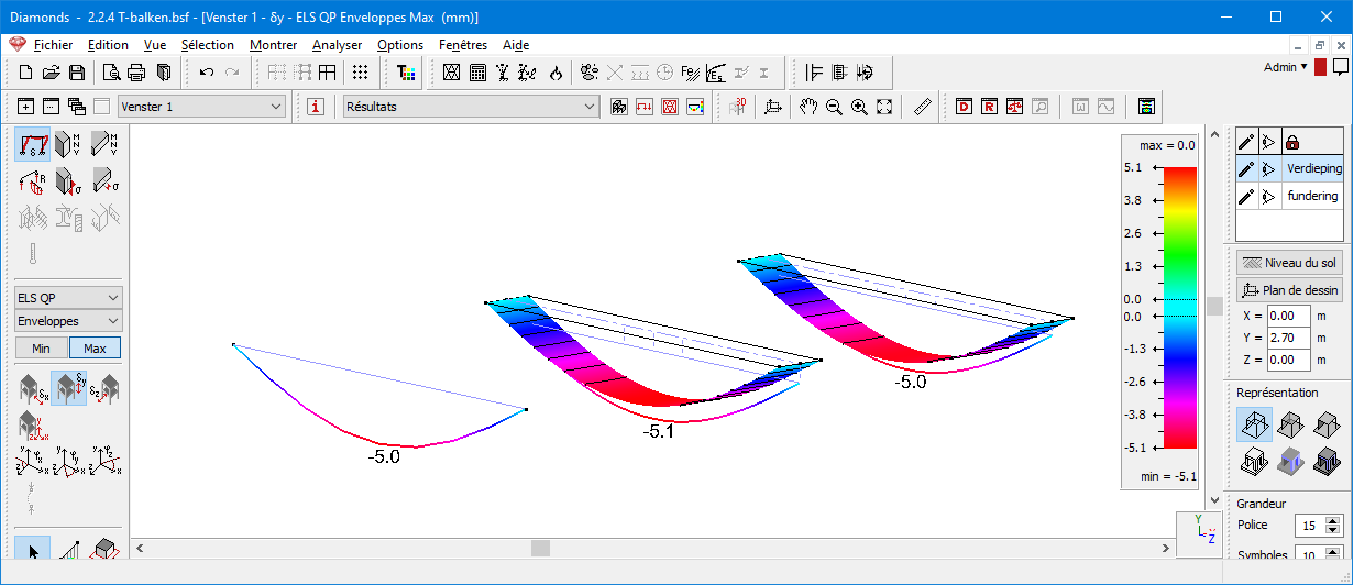 | ||
Reinforcement  : 1st iteration : 1st iteration | 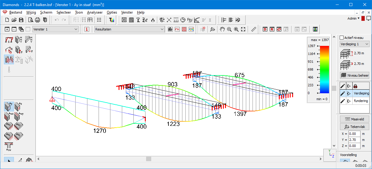 | ||
Cracked deformation  (with creep and axial forces): 1st iteration (with creep and axial forces): 1st iteration | 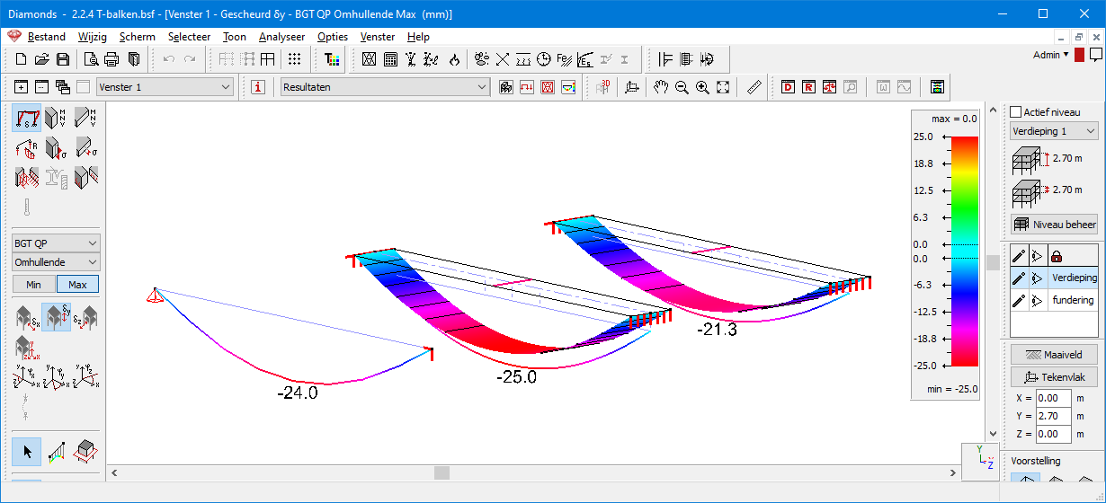 | ||
Elastic analysis  (taking cracks and axial forces into account) immediately followed by a reinforcement calculation (taking cracks and axial forces into account) immediately followed by a reinforcement calculation  : 2nd iteration : 2nd iteration |  | ||
Cracked deformation  (with creep and axial forces): 2nd iteration (with creep and axial forces): 2nd iteration |  | ||
Elastic analysis  (taking cracks and axial forces into account) immediately followed by a reinforcement calculation (taking cracks and axial forces into account) immediately followed by a reinforcement calculation  : 3rd iteration : 3rd iteration | 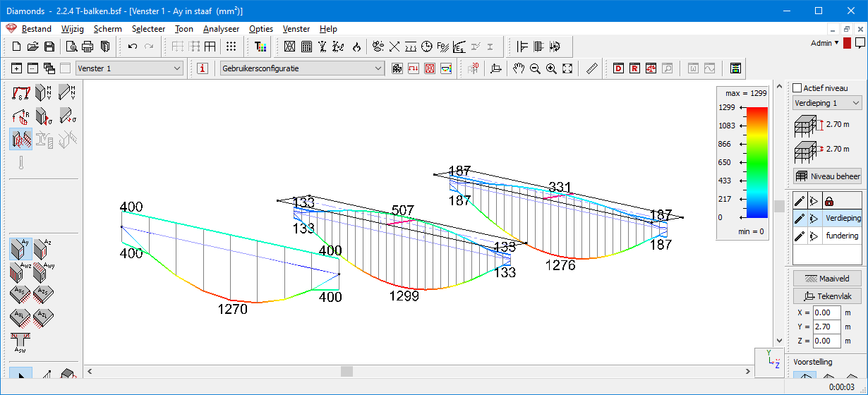 | ||
Conclusion: Way 1 and 3 match the best when it comes to the cracked deformation and reinforcement amount. Way 2 comes close, but is slightly less stiff, resulting in greater deflections and more reinforcement.
Collaboration steel beam – concrete plate
Analogous to concrete, in this section we consider two cases which a steel beam is poured into a concrete plate.
| Reality | Diamonds |
Case 4: préslabs simply supported by a steel beam  | See Case 1 |
Case 5: steel beam connected to a concrete plate using dowels 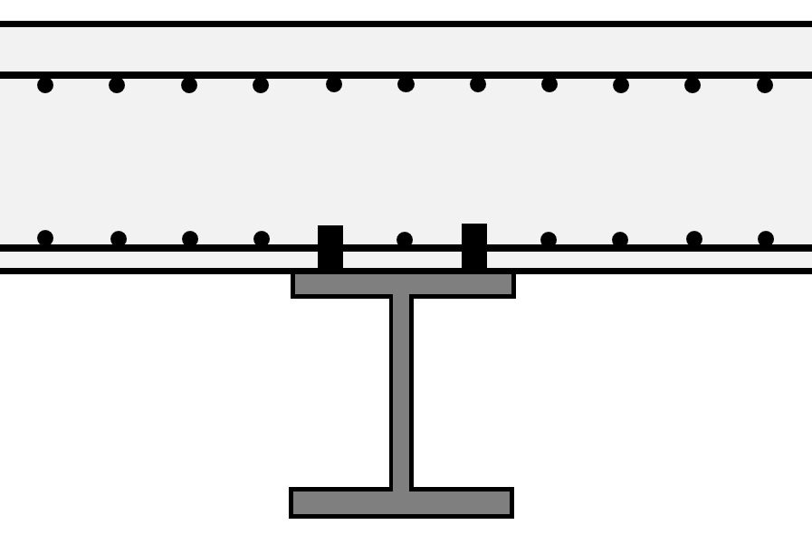 | See Case 3 Set bottom surface plate = top surface beam. |
Note: Diamonds does not support design according to EN 1994 (Design of steel-concrete structures)! With Diamonds, you can determine the internal forces in the concrete floor/steel beam, but during the check, it will apply EN 1992 to the concrete and EN 1993 to the steel.
Non-standard eccentricities
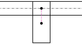
Diamonds creates eccentricities by using rigid links. Rigid links are infinitely stiff elements, which do not have a cross-section or material. Their purpose is to transfer forces between elements.
If you set beam eccentric with the button  , Diamonds will automatically generate the rigid links. The alignment (top surface beam = top surface plate, …) determines the length of the rigid link.
The images below show standard cases. In the images, the rigid link is represented as a pink bar. In Diamonds, a rigid link generated by using the button  , is represented by a dotted line in the same colour as the beam.
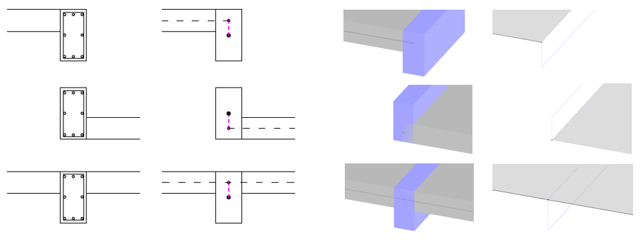
For non-standard eccentricities like the examples below, you manually have to add the rigid link. This is done like this:
- Draw the elements (plate(s) and beam) on the correct level (Y-coordinate). Use the plate and beam axis to determine these levels. The difference in level determines the length of the rigid links.
- At the locations of the rigid links: draw a line, select the line and click on
 . The black continuous line you selected will be a dashed pink line now.
 - The torsion effect is in the rigid links and will go to waste.
- This type of modelling is only advised for smaller models, not for large 3D projects.
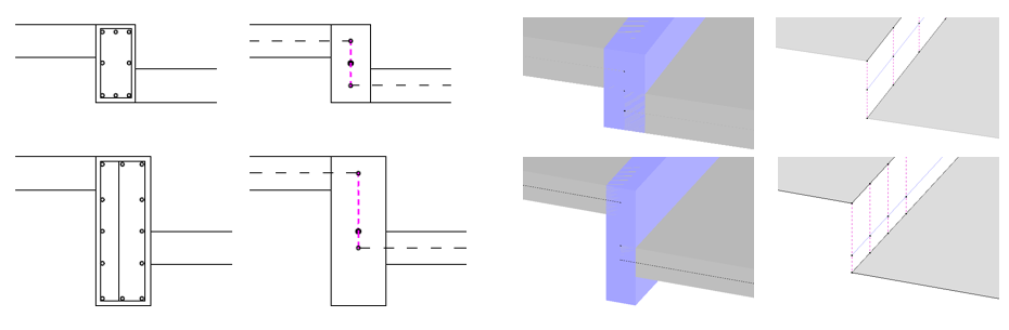
Note: if plates are in different levels, you’ll need a 2D Plates + 3D Plates license!