A rigidity diagram presents the angular deformation (or displacement) according to the applied moment (normal force or shear force) or reaction force. For each bar end and for each internal force, you can define a different function.
Below we discuss how to assign a rigidity diagram to a bar end. The same workflow can be applied to support functions ![]() .
.
- Select the relevant bars and click on
 .
. - Select the option “Function” from the drop down menu next to the relevant internal force.
- Either choose one of the existing functions or define a new one using
 .
.
Let’s assume we want to create a new one. - In the dialogue box that appears, click
 .
.
- Name the function.
- For each sign of the internal force, choose if:
- the internal force cannot be transfered = free
- the internal force can be transfered = fixed
- the internal force can be transfered linear = value
- the internal force can be transfered variable = user defined
- You can save a defined support function in a TXT-file using the button
 . An existing function (TXT format) can be loaded via
  .
.
Below, you will find an example of a rigidity diagram possible for an arbitrary connection.
| Rigidity diagram of a fixed moment connection on a bar end | Rigidity diagram of a deep foundation that can’t bear tension an only 100kN compression |
 | 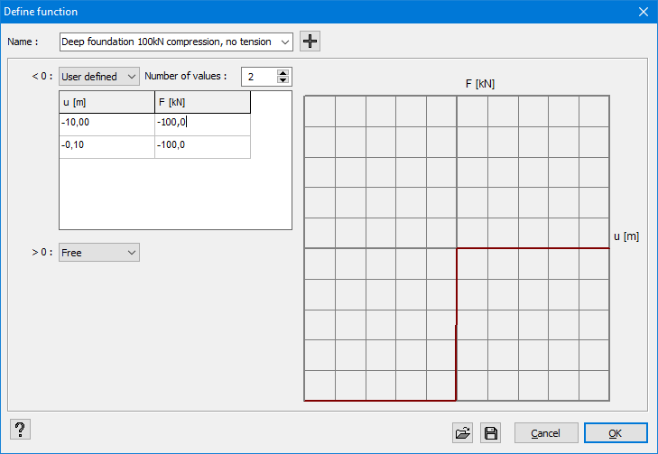 |
| The diagram shows that the rotation rigidity M/φ is constant as long as the applied moment is less than 45,4kNm. Once the moment is exceeded, the rigidity varies according to M. If the moment exceeds 68,2kNm, a plastic hinge is formed because an additional moment produces an angular deformation infinitely large. | The rigidity diagram should lay in the 1st and 3rd quadrant because in the formula F=k∙x the spring constant k cannot take on a negative value. If the function does not have a valid range, a red message will appear below this window. |
